1. (Positioning) When we develop a street light, we must first have a positioning (developing the lighting condition table, such as the general structure of the lamp, power, electrical performance index, luminous efficiency, protective performance, expected weight, etc.), At present, many people don't know enough about LED and LED lighting systems, knowing why they don't know why.
At present, the domestic LED road lighting standards are still officially introduced, and the local standards drafted by Dongguan QS Company have not entered the formal implementation stage. Therefore, this article still starts with CJ45-2006, hoping to play a role in promoting everyone and making progress together.
In the standard, there are clear requirements for the illuminance value and uniformity of the roads of various roads. Take the main road as an example, and the average illuminance is required to be 20-30 LUX. According to your pole height and spacing, you can get roughly one luminous flux. The data. What needs to be trapped by snow is that this is the luminous flux of the luminaire, and the luminous flux of the light source depends on your structure. That is the efficiency of the luminaire.
2, (heat treatment) According to the optical pass, we can find the number of our LEDs and the approximate power of the heat source, and then we can design the heat dissipation system. At present, it is strictly forbidden to use passive heat dissipation (such as adding air). Therefore, it can only rely on its own heat dissipation structure. (Direction: greater heat dissipation surface area, higher dispersion conductivity, heat sink utilization efficiency, insulation solution) The design of the heat dissipation system, we design a temperature rise limit, such as 25 degrees ambient temperature, no more than 25 degrees And then calculate the system thermal resistance. In the material of the radiator, the condition can be selected well. Generally speaking, the heat conduction of 6063 is 205W/M. K, 6061T5 is 180W/M. K, die casting general ADC12 is 40-60W / M. K, the legendary die-casting 1017 can also be more than two hundred, but it has not been used, and no external manufacturers have confirmed it. Good conductivity is very obvious in improving heat dissipation. For the design of the heat sink, a finned heat dissipation structure is generally used to obtain the maximum surface area. It should be noted that the direction of the heat sink is generally selected to be parallel to the road axis. (Some claims that the heat sink is parallel to the road axis, the wind on the road is conducive to heat dissipation, in fact, it is unscientific, the problem of fluid influence can also be known by the actual measurement), the fin design of the radiator is better. The good way should be a small and large structure, and the lower part of the fin thickness is preferably 5mm (depending on the thermal power), and the depth is preferably not more than three to four times the maximum of the fin. The reason is simple and dense. The more severe the heat return, the worse the heat dissipation effect. The thickness of the bottom of the heat sink can be designed to be thinner, such as no more than 3mm, to reduce the weight of the product. A good luminaire design will place the LED section above the fins for this purpose. In the steel glass structure and other practical applications, in order to waterproof, the product often has a closed insulation layer, resulting in a continuous increase in temperature, the hot air is upward, and can be solved according to the specific solution.
The heat generated by the LED is always transmitted faster. Therefore, under the aluminum substrate, we usually add nanotubes or other things to better achieve the soaking and heat conduction effects. The more cost-effective way is to add graphite. For the film, you can ask the supplier for relevant information. In addition, the fins of the radiator are always the lowest utilization rate. In order to improve this problem, some companies have introduced heat pipe cooling. In fact, heat conduction and heat dissipation are two different concepts. Here I am talking about heat pipes, which can be fast. It conducts heat and increases the utilization of some heat radiating fins. Therefore, in the evaluation of cost performance, we can consider and choose according to the actual plan. . It is also possible to combine experimental data by means of software simulation.
3, optical considerations (larger light utilization, light distribution, etc.) optical design, can be achieved by means of related software, such as TRACEPRO, different brands of light-type LEDs, and with different folding lenses, LED spacing, aluminum The thickness of the substrate is quite required, and the optical effect portion can be used to achieve a more reasonable light distribution by means of a soft body. Here we only talk about light efficiency. The design of the luminaire is best to keep the light from the LED closest to the wall of the lamp body from being blocked. The inner wall of the luminaire can be angled at certain conditions. Of course, it can also be treated like chrome plating to get better. Light output. It is more common to add a reflective sheet. The angle of the reflective sheet can be calculated by software. The reflective sheet can increase the utilization of stray light, which can increase by about 15%. Some people say that the LED beam angle is 120 degrees, etc. In fact, we must know that 120 is defined as the maximum light intensity. In addition, when the light encounters an object such as glass, part of it will be transmitted, and some will be reflected back. You can refer to the optical basis.
4, structure, generally speaking, I recommend the tempered glass solution, because the performance is more stable than the PC lens exposure scheme. PC materials will have a lot of weather resistance, and with the stress, waterproof is difficult to solve. In order to suit different installation conditions, it is more suitable for folding, the installation is convenient, the angle is adjustable, and the appearance of the radiator is better.
5, electrical, the most suitable solution for the general 1W LED is still 350mA drive. (Hot, electricity, stability, there are many LEDs for the thin film chip, the higher the current, the worse the reliability) The better way is to open the constant current part separately, each channel has a constant current, it is worth mentioning that Today's LEDs are packaged in Zener, so there is no need to add a Zener.
Metal Core PCB , MCPCB Manufacturing Service
Resume
Metal Core PCB uses a base metal material as the heat spreader portion of the circuit board. Base metals in the MCPCB are used as an alternative to FR4 or CEM-3 boards for the ability to dissipate heat away from critical board components and to less crucial areas such as the metal heat sink backing or metallic core.
The metal core of the Thermal PCB can be aluminum (Aluminum Core PCB), copper (copper core PCB or a Heavy Copper PCB ) or a mixture of special alloys. The aluminum core PCB is most common.
INTRODUCTION
Conventional PCB use FR4 epoxy glass-based material on both sides of a board. However, with the growing popularity of light-emitting diode or LED technology, metal core Printed Circuit Board or MCPCB are being deployed to deal with the increased heat LEDs generate.
Today, metal core PCB are finding greater numbers of applications in the automobile industry, traffic light signal technology, in commercial buildings, shopping malls, and even inside homes.
MCPCB use either an aluminum or copper core with the bottom side of the board serving as the heat sink. MCPCB are also used to dissipate heat in intense power-generating analog circuitry.
Metal core PCB are connected through mounting holes and screws through a box build's chassis. In this arrangement, heat is not only dissipated through the metal core, but it is also transmitted to the chassis. Hence, an LED or analog device-populated board has a considerably larger surface finish for the purpose of dissipating that heat.
But here's a word of caution about using MCPCB – actually two things to be cautious about.
- One, you need to know that making an MCPCB is complex and complicated because a metal layer is laminated with FR4, a glass-base material. Therefore, the chemistry for lamination is different during board fabrication. There is a fair possibility that there would be voids underneath the lamination, if it is not bonded properly.
- Two, a fixture to dissipate the heat from the metal core needs to be carefully defined and designed. Both these concerns demand experience.
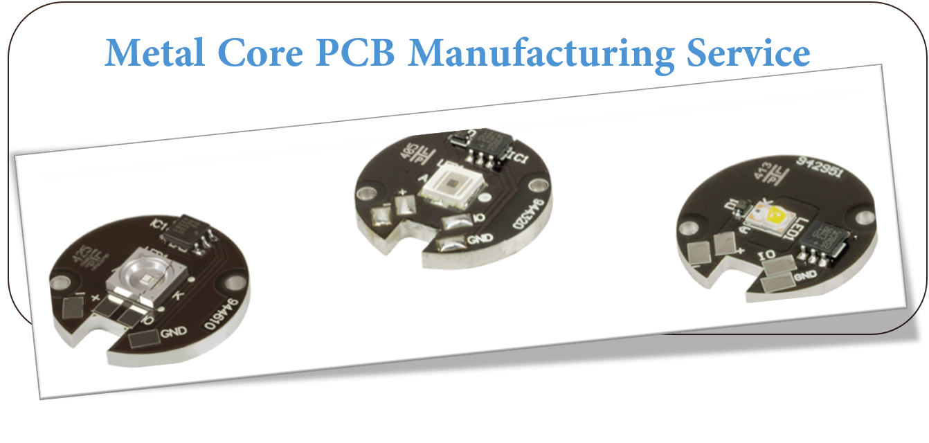
At JHYPCB, we've been doing this for a long time, as one of professional MCPCB/ Aluminum PCB manufacturers from ShenZhen, China. We can produce Metal Core PCB Prototype or aluminum PCB prototyping, aluminium PCB Board for led, No Quantity Requirements, and can successfully guide you through your next MCPCB project. We have worked with over half a dozen LED manufacturers over ten years and have seen enormous amounts of different applications using MCPCB.
Choose us to provide PCB Manufacturing services for you. Contact us immediately.
How Do Metal Core Circuit Boards Differ From FR4 Boards?
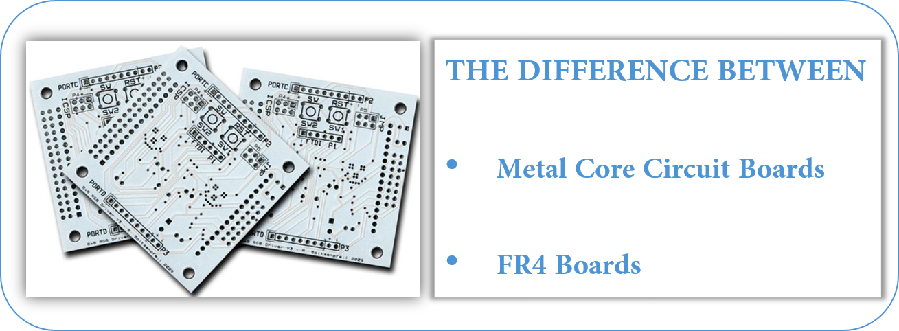
The dielectric material`s thermal conductivity is measured in Watts per meter, Kelvin (W/mK.) A 2.0W rating is fairly common; such material is approximately 6x-7x as thermally conductive as FR4. Best practice is to keep the dielectric layer as thin as possible. Doing so creates the shortest possible path from the heat source to the metal backing plate which is many times more thermally conductive than the dielectric material. Most of the materials come in a very limited range of thicknesses anyway, usually between .003" and .006". You won`t have all that much opportunity to specify something thicker that could diminish the effectiveness of the material at performing its thermal transfer function.
The metal backing plate used on the bottom side is the thickest element in the structure. It is available in several different thicknesses but it is best to use one of the three most common (1.0mm, 1.5mm, and 3.2mm) because they are the easiest to purchase without delays. The metal layer adds rigidity, keeps the circuit flat, and adds enough thickness so that the MCPCB can use the same mounting hardware that would be used for any other standard thickness circuit board. The metal plate side of the board does not receive any surface finish or soldermask.
Metal Core PCB Vs. Fr4 PCB Comparison
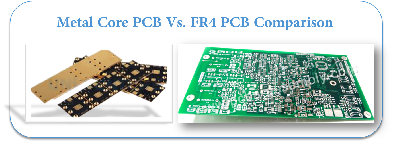
- Conductivity: FR4 has low thermal conductivity, typically around 0.3W, while MCPCB has higher thermal conductivity, ranging from 1.0W-4.0W, most commonly around 2.0W.
- Plated Through Holes: FR4 PCB typically uses plated through holes. Through hole components possible if required. In MCPCB, plated through holes are not available for 1-layer PCB. All components are surface-mounted.
- Thermal Relief: Thermal relief in FR4 PCB typically involves vias for heat transfer. Longer drill cycle, adds many processes. MCPCB materials provide their own thermal relief. Via drilling, deposition, and plating processes are eliminated.
- Solder Mask: FR4 PCB solder mask is typically dark colors (green, red, blue, black.) Usually applied top and bottom. MCPCB solder mask are almost exclusively white for LED boards. Applied to top only.
- Thickness: FR4 PCB has a wide range of thicknesses available using various material combinations and layer counts. MCPCB thickness variation is limited by available backing plate thicknesses and dielectric sheet thicknesses.
- Machining Process: FR4 PCB uses standard machining practices (drilling, routing, v-scoring, countersink, counterbore) while MCPCB uses the same machining as FR4, except that v-score must use diamond coated saw blades for the added strain from cutting into metal.
Material for Metal Core PCB
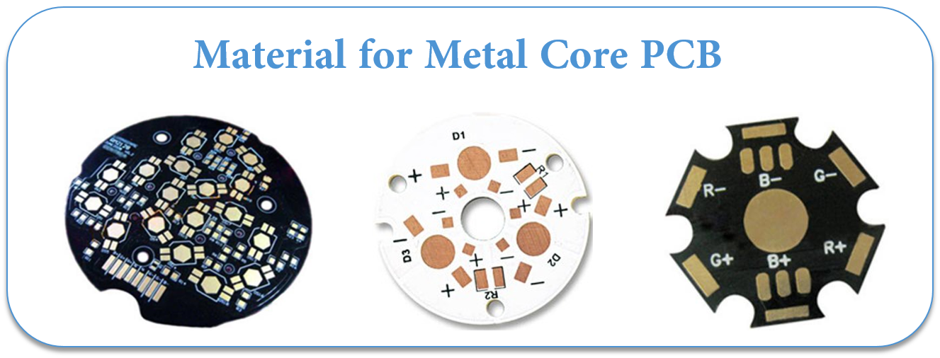
Metal Core PCB means the core (base) material for PCB is the metal, not the normal FR4/CEM1-3, etc. and currently the most common metal used for MCPCB manufacturer are Aluminum, Copper and steel alloy. Aluminum has good heat transferring and dissipation ability, but yet relatively cheaper; copper has even better performance but relatively more expensive, and steel can be divided into normal steel and stainless steel. It more rigid than both aluminum and copper, but thermal conductivity is lower than them too. People will choose their own base/core material according to their different application.
1. Aluminum PCB
Aluminum PCB , also, it is called Aluminium PCB, metal core PCB, MCPCB, IMS(Insulated metal substracte).
Aluminum PCB have 3 parts:
- Circuit Layer (Copper Layer)
- Dielectric Layer(Insulated Layer)
- Substrate Layer(Metal layer)
Aluminum Clad PCB
Available as 1 layer Non-Plated Through Hole (single sided), And 2+ layer Plated through Hole. Ideal application for LED lighting, power supply solutions. Aluminium Clad Benefits Include:
- Lower operating temperature.
- Reduce printed circuit board size.
- Increase power density.
- Extend the life of dies.
- Reduce the number of interconnects.
- Improve product thermal and mechanical performance.
- Combine power and control.
- Improve product durability.
- Enable better use of surface mount technology.
- Expedite heat sinks and other mounting hardware.
- Replace fragile ceramic substrates with greater mechanical durability
About Price:
- Price is based on the requirement of LED PCB
- PCB thickness: 0.6 – 3.0mm, always thickness more ,price higher
- Thermal conductivity: 1.0 – 10 W/m.k , thermal conductivity higher, price higher
- Material factory: Bergquist, Laird ETC, made in US factory that is more expensive than China.
2. Copper Core PCB
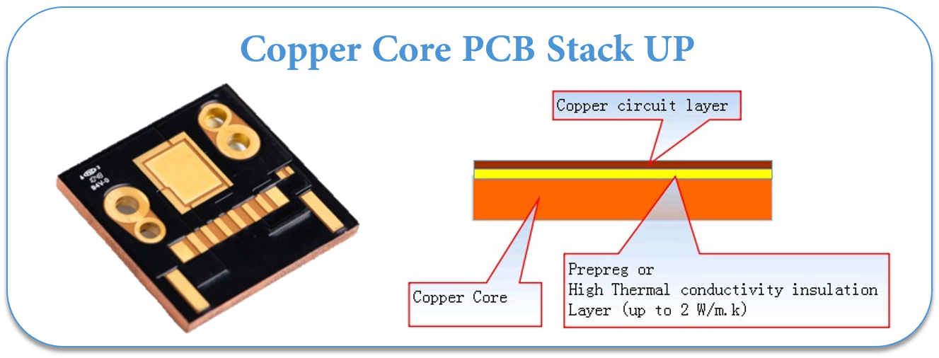
Copper core PCB is a copper substrate + Insulated layer + copper
Copper core PCB is a copper substrate + Insulated layer + copper circuits layer PCB, also, it is called copper substrate pcb, copper based pcb, copper clad pcb.
As a MCPCB manufacturer, we made various Copper core PCB for customers, Which used for High Power LED lighter ( 1000W+ ) and power supply.
In LED field, there are 4 types of Copper based Circuit Board.
COB Copper PCB(Chip on Board copper PCB)
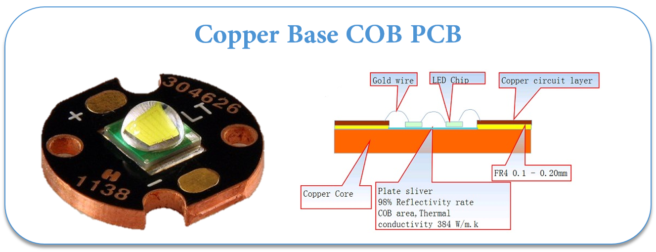
Direct thermal path, no dielectric layer under the thermal path pad.
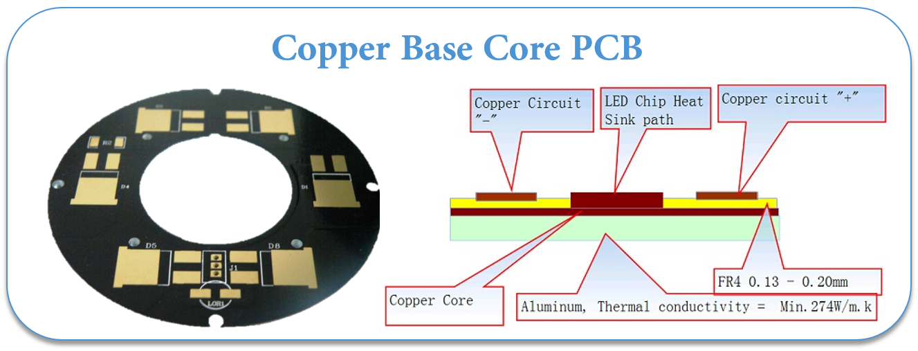
Direct thermal path, no dielectric layer,Aluminum-copper pcb.
The iron-based PCB use material for the base is from special steel, silicon steel and ect in stand of FR4 or CEM1 and can dissipate heat away from critical board components and to less crucial areas such as metallic core or the metal heatsink backing.
China PCB manufacturers becomes more and more professional on Iron-Based PCB.
The Iron-based PCB has all the functions as metal materical and the following particular characteristics:
- Vacancy area convenient for further machinery , procuring and fixing of the base ;
- High mechanic strength, good forther machinery suitable for the assembly heaven electronic parts on its surface;
- Silicon-steel is iron magnetic, and can be applied on micro-motors such as on VTR, FDD.
Metal Core PCB Thickness
The thickness of metal cores in PCB base plates is typically 30 mil - 125 mil, but thicker and thinner plates are possible.
MCPCB copper foil thickness can be 1 - 10 oz.
Benefits of Metal Core PCB Fabrication
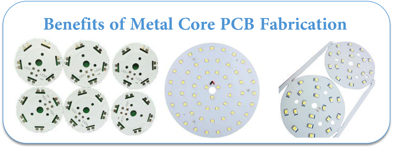
Metal Core PCB Fabrication produces a product that transfers heat up to nine times more rapidly than a typical FR4 PCB. The laminates in MCPCB's dissipate heat which ensures that components which generate heat will remain cooler. This leads to a longer operating life as well as maximized performance for such components.
Applications of Metal Core PCB Fabrication
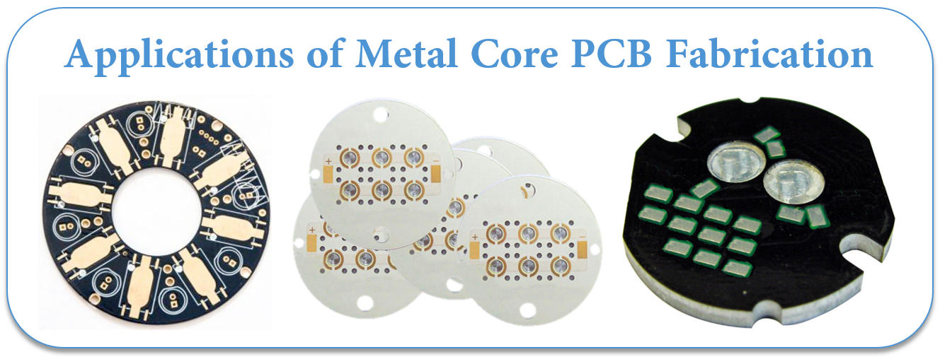
Although LED-based Solid State Light technologies have countless advantages, they inherently produce significant amounts of heat. This makes Metal Core PCB Fabrication helpful for applications like:
- General Lighting
- Automotive Systems
- Power Converters (industrial, telecom, power supplies, and high voltage regulators)
- Photovoltaic
- Street Safety (lighting, streetlights, etc.)
- Back Light Applications
Other applications that are ideal for MCPCB integration are solar panels and motion control applications. We can also combine metal core with our HDI PCB technology. We also offer other advanced circuit technology including Flexible PCB Rigid PCB , and Rigid Flex PCB .
Additional information
Metal Core PCB manufacturing process
Metal Core PCB Manufacturing Capability
LED Lighting and MCPCB (Metal Core PCB)
Understanding the Importance of Metal Core PCBs
METAL CORE PCB VS STANDARD CIRCUIT BOARDS
Metal Core PCB is the best source for the heat transformation
Are Metal Core PCBs the Solution to Your Thermal Management Challenges?
Metal Core PCB
Printable Circuit Boards,Metal Core PCB,Metal Core Led PCB,Metal Core PCB Prototype
JingHongYi PCB (HK) Co., Limited , http://www.pcbjhy.com