When you read the first 6 parts, you have already completed the configuration of the PLC module. Next, let us introduce if you use the Sniffer software to view the PLC data frames transmitted on the power line. Therefore, Sniffer software is like a Spy to detect commands and data frames transmitted on specific power lines, which is convenient for users to evaluate and judge network conditions.
The first step is to download the Sniffer software. The specific downloads have been mentioned in the previous chapters.
After the installation is complete, you will see the following red frog icon on the desktop:
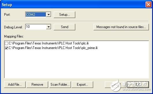
Double-click on the Sniffer software, the following interface will appear, let everyone set up the serial port of the PC used and use the plug-in to resolve Prime.

You can set the serial port information in Setup.
The Debug Level is the level of detail of the display information of the Sniffer software. Debug Level=10 is a detailed display of the details of any command. Debug Level=9 displays all commands but does not perform full resolution. Debug Level=8, compared with 9 just does not display Beacon information, other information is displayed. When the setup is complete, select Send, transfer the command to the DSP, and receive a return from Success.
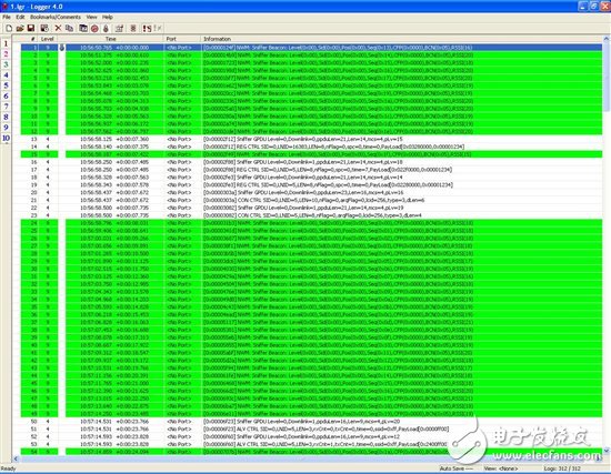
Next, let's take a look at the process of registering, connecting, and sending data for a typical PLC module. Debug Level=9.

The green statement is the Beacon command detected by Sniffer. If Debug Level=8 is used, the Beacon command will not be displayed.
Below I will separate the white statements separately:
1. REG registration process:
1) The command frames of lines 13 and 14 are:
Sniffer GPDU Level=0, Downlink=0, ppduLen=21, Len=14, mcs=4, pLv=15
REG CTRL SID=0, LNID=16383, LEN=8, nFlag=0, spc=0, TIme=0, PayLoad[0x03280000, 0x00001234]
This statement is an UpLink statement, that is, a PLC transfer command frame transmitted from the Meter to the DC side.
DownLink=0, which is UpLink
The SID is the Switch ID because the DC and the Meter are directly connected, and no Switch exists in the middle.
LNID is the Short Address assigned by the DC to the table. By default, 16383 is used first, and 0x3FFF is LNID.
MCS=4, ie the debug mode is BPSK+FEC
The meaning of this statement is REG, that is, the Meter side makes a registration request to the DC side.
2) The command frames on lines 16 and 17 are
Sniffer GPDU Level=0, Downlink=1, ppduLen=21, Len=14, mcs=4, pLv=18
REG CTRL SID=0, LNID=5, LEN=8, nFlag=0, spc=0, TIme=7, PayLoad[0x022f0000,0x00001234]
This statement is a DownLink statement, that is, a PLC transmission command frame transmitted from the DC side to the Meter side.
DownLink=1, which is DownLink
LNID=5, at this time DC has set the Short Address of the table to 5.
3) The command frames on lines 18 and 19 are:
Sniffer GPDU Level=0, Downlink=0, ppduLen=21, Len=14, mcs=4, pLv=14
REG CTRL SID=0, LNID=5, LEN=8, nFlag=0, spc=0, TIme=0, PayLoad[0x02280000, 0x00001234]
This statement is an UpLink statement, which is the REG registration confirmation from the DC to the Meter.
LNID=5, EUI-48=1234
Through the above three statements, the registration process is completed.
2. CON connection process:
From line 20 to line 23, the entire connection process:
Sniffer GPDU Level=0, Downlink=0, ppduLen=23, Len=16, mcs=4, pLv=16
CON CTRL SID=0, LNID=5, LEN=10, nFlag=0, arqFlag=0, lcid=256, type=3, dLen=6
Sniffer GPDU Level=0, Downlink=1, ppduLen=21, Len=14, mcs=4, pLv=19
CON CTRL SID=0, LNID=5, LEN=8, nFlag=0, arqFlag=0, lcid=256, type=3, dLen=4
First DownLink=0, which is UpLink, and the Meter sends a connection request to the table.
Then Receive DownLink=1, the CON confirmation frame that the concentrator replies to the table.
The above two commands complete the connection process.
3.Keep ALV:
But when the table is already registered on the concentrator, the concentrator will continue to send the Keep alive command to ensure that the nodes of the registered connection are alive. For example, the 50th and 53rd lines below:
Sniffer GPDU Level=0, Downlink=1, ppduLen=16, Len=9, mcs=4, pLv=20
ALV CTRL SID=0, LNID=5, LEN=3, rxCnt=0, txCnt=0, TIme=0, ssid=0xff, PayLoad[0x0000ff00]
Sniffer GPDU Level=0, Downlink=0, ppduLen=16, Len=9, mcs=4, pLv=12
ALV CTRL SID=0, LNID=5, LEN=3, rxCnt=1, txCnt=1, time=0, ssid=0xff, PayLoad[0x2400ff00]
The ALV command initiated by the DC first responds to an UpLink ALV acknowledgement frame when the table is received.
4. PNPDU
If a new power-on meter end does not hear the surrounding Beacon, the table will send a PNPDU for help. The specific format is as follows:
Sniffer PNPDU from PNA=0x0000:0000:3412
That is, the distress signal sent by the EUI-48=1234 table, the surrounding SN will help it send its request to the DC through the existing link.
5. PRO
The DC will perform a node's Promote according to the situation, and its Promote will be a Switch.
1) Sniffer PNPDU from PNA=0x0000:0000:1500
2) Sniffer GPDU Level=0, Downlink=0, ppduLen=24, Len=17, mcs=4, pLv=19
Sniffer MAC PRO CTRL Level=0, Downlink=0, SID=0, LNID=28, LEN=11, PayLoad[0x18ff0000,0x00000015,0x04040600]
3) Sniffer GPDU Level=0, Downlink=1, ppduLen=15, Len=8, mcs=4, pLv=23
Sniffer MAC PRO CTRL Level=0, Downlink=1, SID=0, LNID=28, LEN=2, PayLoad[0x07030000,0x00000000,0x00000000]
4) Sniffer GPDU Level=0, Downlink=0, ppduLen=15, Len=8, mcs=4, pLv=14
Sniffer MAC PRO CTRL Level=0, Downlink=0, SID=0, LNID=28, LEN=2, PayLoad[0x07030000, 0x00000000, 0x00000000]
5) Sniffer GPDU Level=0, Downlink=1, ppduLen=15, Len=8, mcs=4, pLv=19
Sniffer MAC BSI CTRL Level=0, Downlink=1, SID=0, LNID=28, LEN=2, PayLoad[0x04500000,0x00000000,0x00000000]
6) Sniffer GPDU Level=0, Downlink=0, ppduLen=15, Len=8, mcs=4, pLv=18
Sniffer MAC BSI CTRL Level=0, Downlink=0, SID=0, LNID=28, LEN=2, PayLoad[0x04500000,0x00000000,0x00000000]
6. Data Transfer
Data transmission must first be initiated by the DC, such as the following command frame
Sniffer GPDU Level=0, Downlink=1, ppduLen=20, Len=13, mcs=4, pLv=17
Sniffer MAC DATA Level=0, Downlink=1, SID=0, LNID=1, LEN=7, LCID=256, PayLoad[0x00900101, 0x32333210]
The latter 0x32333210 is the data that the DC sends to the Meter.
Lithium Ior Batteries For Electric Lifting Platform
Shenzhen Sunbeam New Energy Co., Ltd , https://www.sunbeambattery.com