The production of power amplifier circuit is introduced in the publication. There are gallbladder stones, single-ended push-pull, complicated and simple, but it is balanced in the high-end power amplifiers that are widely used by the world's major manufacturers in tens of thousands of yuan. The amplifiers are rarely introduced. Even if you accidentally see the introduction of balanced power amplifiers, only two common single-ended RCA input amplifiers are put together to amplify the signals on the hot and cold sides. Here I want to introduce you to the production of a true balanced BTL bridged power amplifier. This amplifier can directly input the balanced signal of XLR, or directly input the single-ended signal of RCA without having to go through additional circuits to convert RCA. Convert to XLR signal.
I. Introduction to balance technology
Balanced audio technology is nothing new. It was born as early as the invention of the telephone, and its application enables voice information to maintain a very low noise level for long distance transmission. And that's why balanced signal transmission is now being used in high-end audio: it allows us to transmit information (audio signals) in a way that resists noise and distortion. Two sets of mirrored signals with opposite phase and opposite phase are transmitted simultaneously. That is to say, the two sets of signals are actually not loaded with audio information, but the voltage difference between them.
In order to achieve higher signal-to-noise ratio, greater dynamic contrast ratio and more detailed analysis, the application of balanced amplification technology in audio equipment is a necessary means for many well-known manufacturers, such as Mark LevinsON is a model to use this technology, but Their price is also one of the most expensive in the world.
The sword has a double front, and balanced technology will only have a positive impact on the performance of the audio equipment if it is actually used correctly. If the two signal paths of the audio signal are not accurately mirror symmetrical, then noise and distortion will be added to the audio signal, and the balancing technique becomes a fatal cause of the sound quality. Therefore, in order to discover the many benefits contained in the balanced design, it is necessary to have skilled design and control ability and careful and meticulous circuit structure. However, some so-called "balanced power amplifiers" on the market do not use real balancing technology, just Simply combine the two single-ended input amplifiers.
A balanced amplifier is actually a collection of several amplifiers. Because the signal amplification circuit in the chassis is actually two symmetric balanced amplifiers per channel. This "double balanced" design effectively suppresses common mode noise and distortion while providing balanced load impedance to the front stage. Whether the input is a normal single-ended RCA signal or a truly balanced XLR signal, the two balanced amplifier input stages are first converted into a pair of opposite-end double-ended signals, which are then sent to the outputs of the two amplifiers. level.
The output of the balanced amplifier belongs to the BTL mode, which can easily obtain up to hundreds of kilowatts of output power and only need to use half of the power supply voltage of the general OCL power amplifier circuit, so that the capacitors, transistors and other devices have greater freedom of selection, at low voltage. The work environment also greatly improves security. The output power of this unit is as high as 300W/8Ω.
2. Specific considerations of the circuit
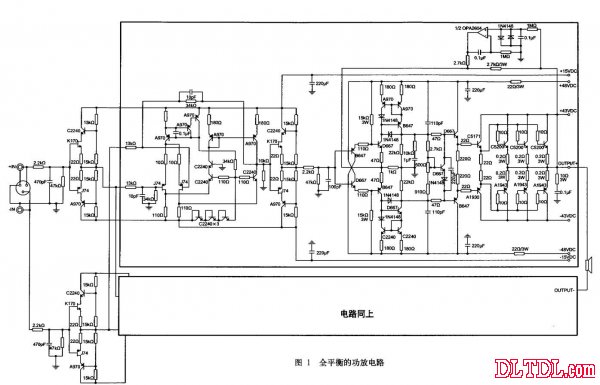
The circuit of this machine is shown in Figure 1. This is a well-structured circuit.


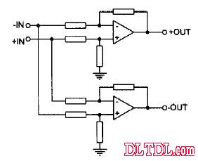
Figure 2 Schematic diagram of balancing the input signal
Figure 2 is a simplified diagram of the circuit operating on the XLR balanced input signal. The visible circuit is formed by two amplifiers cross-connected. The phase of the output depends on the phase polarity of the input signal. Each amplifier is a differential double-ended input mode, so it has a good ability to suppress common mode noise and distortion. The parameters of the two differential amplifiers are the same as those of the circuit. The signals at the output are only opposite in phase and the other characteristics are the same. When the output to the horn, the distortion and noise are cancelled again. Therefore, the fax is extremely high, and the information of the input signal can be highly restored. Both noise and distortion are extremely low.
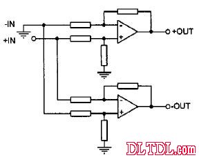
Figure 3 is a simplified diagram of the circuit operating on the RCA unbalanced input signal. Since the input signal is single-ended, one input will be left floating, and this input is shorted to ground to prevent noise intrusion. At this point, the circuit becomes a working mode of the connection between an inverting amplifier and a non-inverting amplifier. Reasonable selection of feedback parameters can make the output signals of the two amplifiers only be polar phases, and the balanced signals are still sent to the speakers. With balanced amplifiers to suppress noise and distortion, there is less chance of canceling noise and distortion than a truly balanced input signal, but it is quite superior in performance.

Figure 3 Schematic diagram of unbalanced input signal
Differential circuit If the input terminal is left floating (no load), the closed-loop gain will decrease, and some circuits may oscillate. Even if no oscillation occurs, the actual operating state of the circuit may not be determined because the output impedance of the previous stage is unknown. Therefore, do not use it alone in the actual circuit. It is necessary to add a level one buffer to the input. Although this will make the circuit appear more complicated. But it makes the circuit work more stable.
The snubber circuit of the input stage in Figure 1 is used for impedance conversion. No matter what kind of preamp is connected, a balanced stable low output impedance signal can be provided for the main amplifying circuit, which ensures the stability of the main amplifying circuit. The symmetry of the gain. This buffer operates in a non-feedback state, and it is necessary to use a circuit with excellent performance to reduce the influence on the sound quality. This machine uses a 渥mann-type buffer.
The main amplifier consists of two identical amplifiers, each of which is cascaded by two separate amplifiers. Located behind the input buffer stage are two differential voltage feedback amplifiers that reprocess the input signal (whether balanced or not) into a double-ended output balanced signal and feed it to the next stage current feedback amplifier. Perhaps some readers will think that from the circuit point of view, the current feedback amplifier can be omitted? Yes, even if the current feedback amplifier is omitted, the circuit still has quite good sound quality, but the author has gone through many experiments and comparisons. I feel that the sound quality is better in this more complicated way. The current feedback amplifier has the advantages of high rate and low distortion (including annoying intermodulation distortion), and the circuit consisting of a voltage feedback amplifier and a current feedback amplifier, the respective circuits work in the most suitable way, and then the gain is properly distributed. Allowing each amplifier to operate at a low closed-loop gain reduces distortion and widens the frequency response.
The current feedback amplifier is a simple and well-performing circuit. After V/I conversion at the input stage of this amplifier, unlike other current feedback amplifiers, the voltage amplification stage is used for amplification. Instead, a pair of up and down symmetrical mirror currents are used. Transmission circuit. In an ideal case, the V/I converted current signal can be transmitted to the output of the stage without loss. In fact, even if the ideal device cannot be used, only a certain degree of accurate matching of the device used can be performed. The author compares the A60 imitation line made with the same device. The A60 line is similar in circuit structure to this circuit. Only in this level is the 渥mann-type voltage amplification stage. The sound of this circuit is more delicate and balanced. The open-loop voltage gain of the current feedback amplifier depends on the ratio of the load (I/V) resistance of this stage to the V/I resistance. The closed-loop gain is only 11.5dB, so the total gain of the entire balanced bridge circuit is input to the XLR balanced signal. 32dB, this is to balance the gain of the unbalanced input signal, because the gain is only half of the XLR balanced input, which is 26dB.
The voltage feedback amplifier is a single-stage amplifier. This circuit was originally applied to Marantz's unique weapon HDAM. The author modified it to reduce the open-loop gain to only 35dB, while the closed-loop gain is only 14.5dB. It is more lively. This amplifier handles low signal levels, so it can be powered by a low voltage of ±15V. The power consumption of the triode is greatly reduced. More models can be selected, and it is easy to select a triode with a suitable sound style. It will be slightly lower.
The output stage uses a three-stage Darlington type with higher input impedance and lower output impedance. In theory, even with a two-stage Darlington-type output stage, the voltage gain stage can be fully driven, but the sound is a combination of sensibility and rationality. Sound production can sometimes not be derived theoretically, but also requires actual listening and adjustment. Under the same circuit device condition, the author has compared the difference between the two levels of Darlington and the third-level Darlington. The performance of the third-level Darlington has a wider extension at both ends, and the low-frequency dive is excellent. Fewer sounds, and music that expresses different speeds is easy. The two-stage Darlington also has its advantages. Because the high and low frequencies extend relatively poorly, the mid-range charm is highlighted, and the low-frequency sense is slightly less, so it is easy to obtain the low-frequency effect of firmness and boxing to meat. This does not mean that the two are poor and excellent. Fans can choose different ways according to their own subjective preferences.
The number of output tubes affects the thickness and balance of the sound. This is not only in this circuit, but also in other circuit modes. When using a single pair of output tubes, the sound is relatively thin, and the low-frequency sense and weight are insufficient, but it is highlighted. The high-frequency charm, which is why some fans think that some European-made low-power amplifiers have beautiful sounds. The goal of this machine is not to highlight the sense of hearing of a certain frequency response, but to fully display the details in the sound source. Therefore, it is necessary to have sufficient driving force to drive most of the speakers. Each pair of bridge arms uses 3 pairs of output tubes in parallel. It is the lowest guarantee.
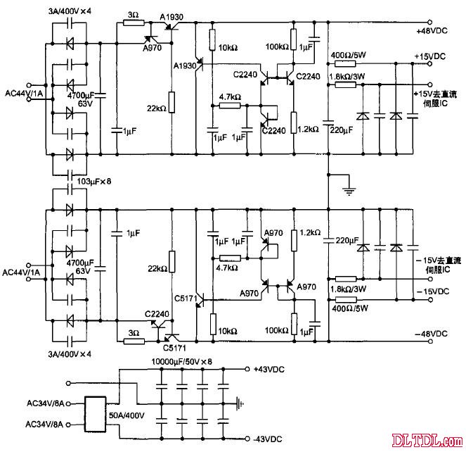
This unit uses a shunt regulator circuit, as shown in Figure 4. The author has produced a number of circuit-mode regulated power supplies. In this way, the sound is the most balanced, the fax is better, and the circuit is simple. In the past, I used an LED light-emitting tube with a triode to change the diode for temperature compensation. The output voltage was only affected by temperature, and the rate of change was only 5‰, which reached an excellent level. Fans may find that the regulator's voltage regulator's reference regulator uses only one diode to change the diode, which will make the output voltage drop due to temperature rise, but considering the power amplifier circuit does not require high voltage values, The stabilized voltage is correct, and the sound quality is relatively pure, the medium and low frequency thickness and strength are also improved, and the high-frequency detail reproduction is not affected, and the overall sound quality is more delicate. This also reflects the emotional side of the sound, can not simply look at the indicators, but also needs more listening and practice.
More and more fans are paying attention to the power supply during production. This is the right direction. All signals are generated from the power supply, so the power supply should be treated the same as the audio amplifier circuit. Paying attention to the power supply is not simply increasing the capacity of the transformer and the filter capacitor. This only ensures that the power supply can continuously supply energy to the load. However, in a country with serious power pollution, such a power supply is like turbid water. Although some long-established machines only do this, in developed countries in Europe and America, power pollution is not as serious as domestic ones. Therefore, it is necessary to use a regulated power supply to clean the power supply according to local conditions. This is indispensable. In the past, I used to compare other power circuits, use a regulated power supply, use a battery-powered power amplifier, and found that the sound of the power supply is the most ambiguous, with less detail. The sound is clear when using the battery, and the details are rich. The state response is good. The use of a regulated power supply is close to the use of a battery. This means that the interference of the power supply cannot be eliminated by simple filtering. The power supply makes the sound quality unclear and the small signal is overwhelmed.

Figure 4 parallel regulator circuit
III. The desired result
The circuit of this machine is quite mature and stable, so as long as the components are correct, the success rate is 100%, and there is no need to worry about the oscillations that need to be adjusted. In terms of component selection, it is desirable to use some devices with better quality and higher precision. The resistors are better with Dale. The resistors on the feedback are best used with Hocle. The triodes are best paired and the small triodes are BL. The transformer uses a 650W ring cow per channel.
Before power-on, adjust the adjustable resistance of the output stage bias circuit to the maximum resistance. Use the DC power supply with limited current function to test the circuit. Confirm that there is no problem and press the transformer. The sound of each output tube is 50mA. Great, more than a lot of pure class A amplifiers. The input uses a balanced socket, an inverting input RCA socket and a non-inverting input RCA socket, so it can be input from different sockets with opposite output phases during RCA input, like some DIY bile DACs, bile preamps, etc. If the single-tube type A is used, the SRPP circuit is 180° out of phase, and the signal is re-acquired from the inverting input of the unit to regain the correct phase. When using the RCA input, plug an unused short-circuit plug into the unused RCA socket to reduce the noise induced by the input no-load.
The device used will have some effect on the tone. I have made two different capacitor versions, one based on Evox and the other on Wima. Wima is difficult to use, and many fans say it will make the sound rough and hard. In fact, this is not the case. Wima capacitors have excellent performance and less dyeing, and the parameter structure of the circuit and other devices have a major influence on the sound quality. If the parameter structure of the circuit and the selection of other devices are not good, the sound is naturally not good, and the sound quality is quite good. Like Mark Levinson and some American-made machines, I like to use Wima capacitors. Another reason is that the country is full of a lot of inferior imitation Wima capacitors, and some manufacturers deliberately copy, after all, it is much higher than the price of domestic brand-name capacitors. Enthusiasts should choose a business with integrity when purchasing, otherwise the loss of money is small, and the elaborate machine will have a greater impact on confidence due to the use of fake goods, which also affects the feeling and confidence of fans using Wima capacitors. This machine with Wima capacitors has more dynamic dynamics, rich sound and better layering.
The sound performance of the XLR balanced input is the best, and the RCA unbalanced input is also good, but I think the sound quality at this time is only about 70% of the XLR balanced input. This machine was sent to Mr. Cao, an audiophile in Hong Kong. He commented: "(I) has a fever for more than 15 years, because of the coldness of life (meaning å啬), did not buy expensive equipment, always pegged to the imported products within 20,000 yuan, should also be familiar with this Price with the production and performance of the product... Personally think that in addition to the chassis technology and the imported goods are fine, the production scale and overall performance have exceeded the above price equipment, the sound quality is high, the sound is beautiful and gorgeous, the sound is smooth and natural, and there is still movement. The sound of the sound is gorgeous and smooth when listening to string music. Listening to the symphony orgasm is the most powerful.
China Fast Car Charger,Dc Fast Charging Stations manufacturers, welcome Electric Vehicle Charging Pile,Electric Charging Stations purchasers from worldwide to visit our site.
Fast Car Charger,Dc Fast Charging Stations,Electric Vehicle Charging Pile,Electric Charging Stations
Shenzhen Hongjiali New Energy Co., Ltd. , https://www.hjlcharger.com