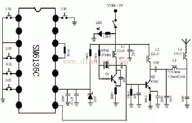
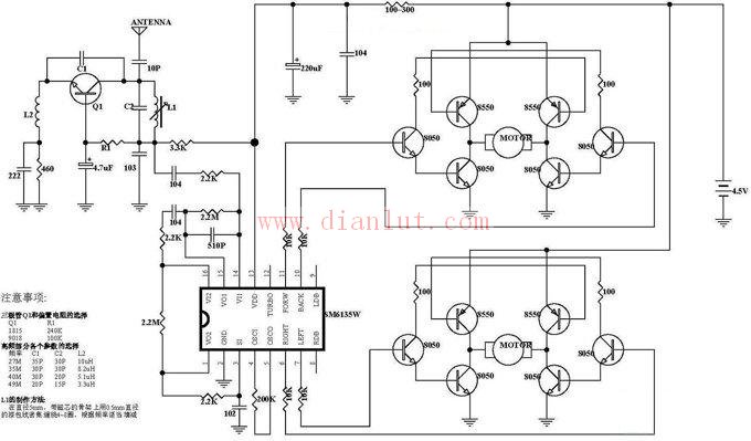
The following is a circuit diagram of the transmission and reception circuit diagram of the radio remote control car.
Principle 1: Radio remote control car transmission schematic

Principle 2: Radio remote control car receiving schematic

GPS /Glonass/Beidou/Galileo Antenna
1. According to the polarization mode, GPS Antenna can be divided into vertical polarization and circular polarization. With current technology, vertical polarization is not as effective as circular polarization. Therefore, GPS antennas will be circularly polarized except in special cases. 2. GPS antenna is divided into internal antenna and external antenna in the way of placement. The location of the antenna is also important. At this time, the antenna is basically isolated from the interior of the whole machine. EMI is almost not affected. The satellite reception effect is very good. Now, with the trend toward miniaturization, GPS antennas are mostly built in. In this case, the antenna must be higher than all metal components, and the shell must be electroplated and well grounded, away from EMI interference sources, such as CPU, SDRAM, SD card, crystal oscillator, and DC/DC. The use of GPS in cars will become more common. And the car casing, especially the car explosion-proof film can seriously block the GPS signal. An external antenna with magnets, which can be attached to the roof, is essential for onboard GPS. GPS antenna structure
GPS Antenna,GPS Antenna for Car,GPS Antenna SMA,GPS Antenna Fakra,Inside GPS Antenna
Yetnorson Antenna Co., Ltd. , https://www.xhlantenna.com