The positive and negative poles of the crystal diode can be discriminated as follows:
1. Look at the symbol mark on the housing: usually the symbol of the diode is marked on the outer casing of the diode. One end marked with a triangular arrow is a positive electrode and the other end is a negative electrode.
2. Look at the color points marked on the housing: on the housing of the point contact diode, usually marked with a color point (white or red). Except for a few diodes (such as 2AP9, 2AP10, etc.), the end of the generally marked color point is positive.
3. See the stylus through the glass: For the point contact type glass casing diode, if the mark has been worn away, the paint layer (black or white) on the outer casing can be lightly scraped off a little, and the metal stylus is seen through the glass. The end is an N-shaped cymbal. The one with the metal stylus is the positive pole.
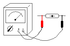
4. Use the multimeter R*100 or R*1K file to arbitrarily measure the two leads of the diode. If the measured resistance is only a few hundred ohms (forward resistance), the lead of the black test lead (the positive electrode of the battery in the multimeter) is positive. The lead of the red test pen (the negative pole of the power supply in the multimeter) is the negative pole. (see picture 1) 
figure 1
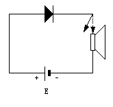
5. Use the battery and the speaker to identify the positive and negative poles of the diode: as shown in Figure 2. Connect a battery and a speaker (or earphone) to the diode under test to form a series circuit. Then, one end of the diode is intermittently touched to the horn, and then the diode is turned down and measured again. The one that is connected to the positive electrode of the battery is the positive electrode and the other is the negative electrode. 
figure 2
To determine the quality of the diode, the following methods can be used:

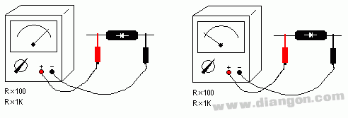
Figure 3a Figure 3b
1. Use the multimeter R*100 or R*1K to measure the forward and reverse resistance of the diode. As shown in Figure 3, the forward resistance of the 2AP diode of the point contact type is about 1K, see the earth 3a, and the reverse resistance should be above 100K. See Figure 3b; the silicon surface contact type 2CP diode has a forward resistance of about 5K and the reverse phase resistance should be above 1000K. In short, the smaller the forward resistance, the better, and the larger the reverse resistance, the better. However, if the forward resistance is too large or the reverse resistance is too small, it indicates that the detection and rectification efficiency of the diode is not high. As shown in Figure 4, if the forward resistance is infinite (the needle does not move), it means that the diode is internally open; if the inverting resistor is close to zero, it indicates that the diode has broken down. Diodes that are internally broken or broken down cannot be used. 
Figure 4
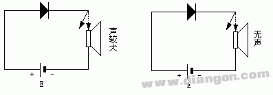
2. If there is no multimeter, the battery, speaker (or earphone) can be connected in series with the diode to be tested. When the negative terminal of the diode is connected to the positive pole of the battery, the positive terminal is connected in series with the horn and then connected to the negative pole of the battery (reverse connection). If the speaker is intermittently connected, if the speaker emits a large "giggle" sound, it indicates that the diode has been transmitted (as shown in Figure 5a). In other words, if the diode is continuously turned on in the forward direction (as shown in Figure 5b), the speaker has no sound, indicating that the diode is internally open.

Figure 5a Figure 5b
Tws Sport Earphone,True Wireless Earbuds,Tws True Wireless Stereo,Tws True Wireless Earbuds
Guangzhou YISON Electron Technology Co., Limited , https://www.yisonearphone.com