In order to improve the fuel economy of new cars, more and more functions in automobiles are being electronically reduced to reduce the continuous load of internal combustion engines. These features include water, oil and fuel pumps, valve actuation and power steering. As the electrical load is transferred from the engine to the car battery, the need to maintain battery charging and normal operation becomes even more important.
This article refers to the address: http://
For automotive electrical system designers, the battery sensor is an extremely important component: it is connected to the electronic control unit (ECU) of the electrical system via the LIN bus for displaying the state of charge, normal status and functional reading status.
Typically, the battery sensor is located at the negative side of the battery and is used to measure low side current, voltage, and temperature. The battery sensor works by capturing battery current and voltage values ​​at a sampling rate of 1 kHz. This requires extremely accurate measurement of the state of charge and the ability to dynamically track battery impedance. The shunt-based low-side current detection zero-offset high-precision measurement system operates synchronously with the voltage detection function to meet accuracy requirements with almost zero insertion loss. It is suitable for use in harsh automotive environments.
But what happens if the battery sensor is on the positive side and is operating as a high side sensor? Automotive designers will be able to change and optimize the control network topology, for example, by using battery sensors to measure various parts of the power system. It can also reduce bill of materials (BOM) costs by combining related modules, such as distribution boxes, and connecting a shared microcontroller. This is also in line with the trend of automotive design using fewer and more concentrated ECUs.
By using a charge pump level shifting technique, or using an electrically isolated power supply and digital communication components, it is theoretically possible to move the existing low-side battery sensor to the high side, increasing the sensor's power supply beyond the battery's 12V level. . The first method will be affected by power pulses and requires complex and difficult EMC countermeasures. The second method, for its reliability and power consumption issues, requires the use of expensive discrete components.
Today, a new automotive battery test method developed by Austrian Microelectronics will enable the accuracy, precision and robustness of high-side battery testing required by automotive manufacturers. It ensures accurate signal extraction from a 100μΩ shunt resistor on the high side of the battery, suitable for current ranges from 1mA to greater than 1kA with virtually no insertion loss. More importantly, it achieves standby current, voltage and temperature monitoring modes at very low current consumption (approximately 80μA) and does not disconnect the battery during normal operation - a critical requirement for automotive battery sensors.
Its implementation is not as difficult as EMC because the common mode rejection and ADC filter not only eliminates EMC, but the output of the system can also reduce BOM cost via an existing ECU.
Shunt resistor specification
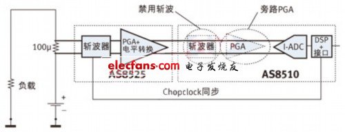
This article focuses on signal conditioning, power management, and communication layers for sensors. Current sensing requires the use of a low insertion loss 100μΩ shunt resistor that is connected to the battery positive terminal of the series load (see Figure 1).

Figure 1: Austrian Microelectronics Dual Chip Sensor Interface Function Module for High Side Automotive Battery Testing
(load, chopper, PGA+ level shifting, disable chopping, bypass PGA, DSP+ interface, Chopclock synchronization)
As mentioned above, automotive battery sensors have very high accuracy requirements. Obviously, the temperature drift of the shunt resistor must be very small, as any shunt resistor value drift will directly affect the current reading produced by the sensor.
For this reason, the Austrian microelectronics circuit described here uses a 100μΩ BAS shunt resistor from Isabellenhuette. This shunt resistor uses a manganese-copper alloy as a resistive element. The temperature coefficient is not only low, but equally important, its Seebeck coefficient is similar to copper. This means that when inserted into a copper track, the thermocouple effect due to signal generation is negligible. The shunt resistance value is also small over time and can be foreseen.
Extremely wide measurement range
The most challenging aspect of automotive battery sensor design is the very accurate measurement over a wide current range of -1 mA to 1 kA. This requires a sensor interface with a measurement range greater than 100mV and a resolution better than 1μV.
The main features of this measurement system are:
* Very low noise
* High linearity
* zero offset
Non-offset measurement systems typically employ continuous offset cancellation techniques. The high-side battery sensor solution mentioned in this article implements a zero offset of the car through a series of signal conditioning functions:
* Chopper analog sensor signal
* Amplify and level shift chopping signals
* For digitized signals
* Digital domain re-wave
This architecture helps eliminate the low frequency noise components of the entire measurement path of the offset and sensor interface.
As shown in Figure 1, the analog chopper is located at the input pad of the AS8525, which receives the shunt signal at a nominal 14V common-mode input voltage. The chopped signal is amplified by a programmable gain amplifier (PGA), level-shifted to a low common-mode voltage, and forwarded to the AS8510 analog-to-digital converter (ADC). (In this application, the internal chopper of the AS8510 must be disabled and the PGA must be bypassed.) The dedicated Chop_Clock pin must be enabled to support synchronization of the averaging and chopping functions.
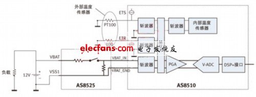
For voltage measurements, the battery voltage is attenuated by a precision resistor attenuator inside the AS8525 and forwarded differentially to the second data acquisition channel of the AS8510 (see Figure 2). This channel can be used to multiplex the input channels of external or internal temperature sensors.

Figure 2: Voltage detection of the high side car battery sensor.
(load, external temperature sensor, chopper, internal temperature sensor, DSP+ interface)
From the division of functional modules, the AS8525 has every function related to the actual battery voltage, but the low-voltage signal conditioning function is implemented in the AS8510. Fabricated from 0.35-micron 60V CMOS technology, the AS8525 also provides two low-dropout regulators (LDOs) with power-on reset and voltage monitoring, as well as a LIN bus transceiver and precision voltage attenuator. System designers can choose to separate the analog signal from the digital portion of the AS8510 from the signal from the microcontroller using two independent LDOs in the AS8525.
There are two options for temperature sensing: If the sensor is located at the battery pole, the AS8510's internal temperature sensor can pick up the battery temperature through the battery pole, shunt resistor, and PCB. Alternatively, if the electronic part of the sensor is located in another compartment away from the battery, an external temperature sensor is used. The typical current measurement error produced by the large common mode input signal is 0.05%/V. Since the common-mode input signal for the shunt resistor is the same as the battery voltage and the battery voltage is measured synchronously with the current, this error can be corrected using the software of the external microcontroller. The exact value of the common mode error can be captured by tail line calibration: a reference current is applied to the two differential common mode shunt voltages as a calibration factor to measure the deviation and store the exact value.
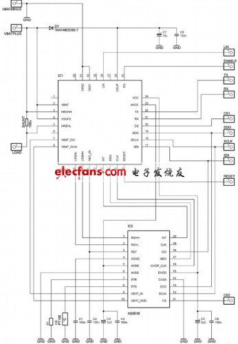
Figure 3: High-side car battery sensor circuit diagram using Austrian Microelectronics AS8525 and AS8510 The high side battery sensor circuit with SPI to microcontroller output is shown in Figure 3. In terms of PCB design, shunt resistors should be connected to HRSHH and HRSHL with very short and symmetrical signal lines. Any kind of coupling from other sources must be avoided. The best result is to solder the AS8525 and AS8510 directly to the shunt resistor on the PCB. The shunt resistor is heated by the hot plate below until the solder melts. In order to achieve good EMC performance, all differential signal lines need to be close together and as symmetrical as possible. in conclusion The AS8510 + AS8525 chipset provides signal conditioning, power management and communication layers for 12V high-side current, voltage and temperature sensing systems at typical sample rates of 1kHz. By using a 100μΩ shunt resistor, the resolution can be reduced to 2.5mA in the current range of 1,600A with an accuracy better than 1%. The voltage measurement accuracy is 12 bits or higher. The standby current is typically 80μA in current monitoring mode. It is fully compliant with all applicable automotive standards. The chipset's load dump protection is up to 42V and provides reverse polarity protection for shunt and battery voltage detection input. |
Earphone Headphone
Earphone Headphone,Best Earbuds Under 1500,Boult Bluetooth Earphones,Apple Bluetooth Headphones
Pogo Technology International Ltd , https://www.pogomedical.com
