In our lives, we use electricity all the time. At home, we have air conditioners, electric water heaters, induction cookers, small mobile phones, desk lamps, razors, and all use electricity as energy. Although the power is easy to clean, with the popularity of electrical products, the total power consumption of the society is also very large. What's more, most of the electricity we use is at the expense of non-renewable energy sources (such as coal) and polluting environments (such as waste batteries). Therefore, the awareness of saving energy is far more than saving a few dollars and a few cents. It should be thought that this is a contribution to the sustainable development of mankind. This is the responsibility of electronics enthusiasts.
In the past two years, "Electronic Production" and "Radio" magazine often published articles on self-made high-power LED flashlights. After reading it, I couldn't help but itch. So I bought several 1W LEDs and AMC7135 drive circuits online. After the goods arrive, they are welded according to the circuit diagram in the article. With these two components, I soldered a button switch and the circuit part was completed. Then there is the power part. I don't have any power on hand. There is only one battery box with two 5th batteries. So I put two batteries and connect them to the circuit. When I press the switch, the LED lights up. To be honest, an LED actually has such a high brightness, I really didn't think of it. The schematic is shown in Figure 1, and the wiring diagram is shown in Figure 2. 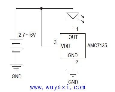
Figure 1 Schematic diagram of high power LED circuit 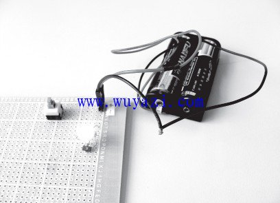
Figure 2 The actual wiring diagram of the high-power LED. Since the finished circuit board and the flashlight are not purchased, the circuit is always placed there after the circuit is completed. At the beginning of the first few days, it is time to connect to the power supply to enjoy it. After a long time, there are more things. Gradually forget it.
I took my child to see my parents last week. My father took the children out to play. I sat in the room and chatted with my mother. I picked up a small flashlight on my mother's desk. The mother said that the flashlight was just broken. I don't know. what reason. I tried the switch, and if it didn't light up, I said to my mother, I took it back and repaired it, and then repaired it and sent it to her.
This is an old-fashioned small-bulb flashlight with two 5th batteries. I was thinking when I was talking to my mother. Can I transform it into a high-power LED flashlight? Back home, I turned this flashlight on, and its structure is shown in Figure 3. 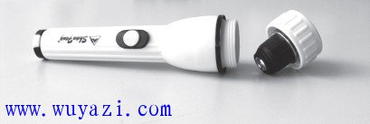
Figure 3 The structure of the flashlight can be seen from Figure 3 and Figure 4. The small light bulb is placed in a lamp holder on the head of the flashlight. If the light bulb is taken out directly, how can the LED be placed inside? I took the positive and negative poles of the LED circuit out with wires and put them in the lamp holder of the small bulb. But how to put them is not suitable. What is important is that the LEDs cannot be fixed. I couldn't think of a way at the moment, so I put the flashlight aside. 
Figure 4 The internal structure of the lamp head This Sunday, I have to go to my parents' home again, think of the flashlight, can't sleep in the morning, get up and start to play with it again. I picked up the broken light bulb and found that the glass lamp holder and the metal lamp holder had loosened and was about to fall. So, if I had a good idea, could I put the LED on the lamp holder of this small light bulb? Just do it, I broke the glass bubble on the small bulb and cleaned it, leaving only the metal lamp holder part of the small bulb, which showed two leads. There is also a small ceramic column between the two leads, and the small ceramic column also knocks it off, leaving only two leads, which can be used. Then find a hole plate, cut a small piece with scissors, put it on the small lamp holder, and then trim the hole around the hole plate with scissors until it is cut to the same size as the outer diameter of the bottom of the small lamp holder. A small board is ready, see Figure 5. 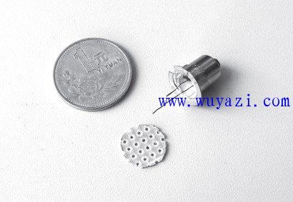
Figure 5 Lamp base and circuit board Place this circuit board on the small lamp holder. Note that the copper surface must be placed outside, and the two leads of the small lamp holder are just pulled out from the pin sockets in the middle of the circuit board. See Figure 6. 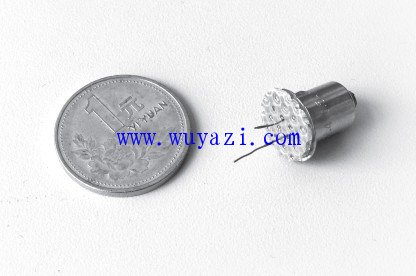
Figure 6 The lamp base and the board are placed here. The latter is easy to do. Just solder the LED circuit from the front to the board. Originally, the two pins of the LED light are horizontal. To solder to the copper surface of the circuit board, simply fold the two pins into 90° and let it stand on the circuit board. When soldering, be careful to solder the LED light and solder it to the middle of the board.
After soldering, I found that the LED circuit is almost exactly the same as the small bulb. However, when it was put into the flashlight, there was a problem. The original metal seat of the bulb was not fixed with the circuit board. When the bulb was placed, the circuit board also turned, which caused the two positive and negative leads in the bulb to be stirred together. then what should we do? I took the modified small light bulb and observed it carefully. I found a small gap in the wall of the small lamp holder. A wire was drawn from the inside and welded to the outer wall below the notch, and there was a solder joint on the outer wall. So I found a wire and used this gap to solder the board to the base of the bulb, so there was no problem in the flashlight.
I loaded two new 5th batteries, and the old-fashioned light bulb flashed again. This is not a normal flashlight, it is a real high-power LED flashlight. For this reason, I made a comparison. The same two new No. 5 batteries are connected to the small light bulb used in the flashlight. The current is close to 500mA, and the current is only a few dozen milliamperes, which is connected to the high-power LED circuit of 1W. It is said that the LED light not only saves electricity several times more than the small light bulb, but also has a much higher brightness.
Old-fashioned light bulb flashlights may be available in many homes. With the popularity of LED flashlights, small light bulb flashlights are no longer used. Some of these flashlights are still very good at work, and it is a pity to abandon them. Now with a single high-power LED, and the drive circuit is so simple, this creates a convenient condition for us to transform the small bulb flashlight. In fact, the structure of this type of flashlight is also various, and as long as you use your brain, it is not difficult to transform it.
Coaxial Power D-Sub Solder Cup
Coaxial Power D-Sub Solder Cup Contacts with Mixed or Full Layout
Transmit Radio Frequency Signals
The Coaxial D-Sub have like the Power D-Subr replaced the two rows in a Standard Density connector with a coaxial contact that take up about the same size as the two rows of signal contacts. The Coaxial D-Sub is exactly the same size as the Standard Density connector but instead of example 9 positions of signal pins it has 2 power contacts , or instead of 37 positions of signals it has 8 coaxial contacts.
The Impedance for the coaxial contacts are 50Ω or 75Ω
The Coaxial D-Sub with Mixed Layout mixes both coaxial contacts and signal contacts in the same connector. For example the same size as a 15 position Standard Density D-Sub you can have what we call a 7W2, which means there is 7 contacts where 2 of them are coaxial contacts, which means there are 5 signal contacts, so 5 signals and 2 coaxial. See the Layout in the Tech Specs on the bottom, there are a lot of combinations of the Mixed Layout alternative.
Antenk's Coaxial D-Sub connectors are available in 5 standard shell sizes with 23 multiple contact arrangements. These reliable, robust combination d-sub connectors allow a combination of signal and coaxial contacts in cable mount, vertical board mount & right angle board mount termination type variations.
Features
Coaxial d-sub for a variety of applications in cable mount.
Signal contacts come pre-loaded. Coaxial contacts supplied - Not Pre-Loaded.
Available in 5 standard shell sizes with 23 multiple contact arrangements: 1W1/ 2V2 /2W2 /3V3/ 3W3/ 5W1/ 5W5
/ 7W2/ 8W8/ 9W4/ 11W1/ 13W3/ 13W6 /17W2/ 17W5 /21W1/ 21W4/ 24W7/ 25W3 /27W2/ 36W4/ 43W2/ 47W1
Allows combination of signal and coaxial d-sub contacts.Materials
Shell: Steel, nickel plated
Insulator: PBT + 30% fiber-glass - Black, U.L. rated 94V-O
Contacts: Brass - Gold flash over nickel
Notes
Panel Cut-Outs
5W1 = Standard 9 Pin Shell
3W3 / 3W3K / 7W2 / 11W1 = Standard 15 Pin Shell
5W5 / 9W4 / 13W3 / 17W2 / 21W1= Standard 25 Pin Shell
8W8 / 21WA4 = Standard 37 Pin Shell
Other Contact Arrangements Available Upon Request.
Coaxial D-Sub Connector, Coaxial D-Sub with Mixed Layout, Coaxial D-Sub with Mixed with Full Layout,Coaxial D-Sub Male, Coaxial D-Sub Female
ShenZhen Antenk Electronics Co,Ltd , https://www.antenk.com