For small currents, we can directly measure them with a multimeter; but for large currents, directly measuring them has a considerable risk factor, and there is a big hidden danger to the operator's personal safety. How to realize the measurement of large current? This is the time for the current transformer to show its talents. It can convert large current into a small current according to a predetermined ratio, and measure the small current and then restore it to a large current to achieve high current safety. Sex measurement. So how does the current transformer achieve this function? What is the principle of the current transformer ? Let's take a look at it~
First, the principle of current transformer - - Introduction
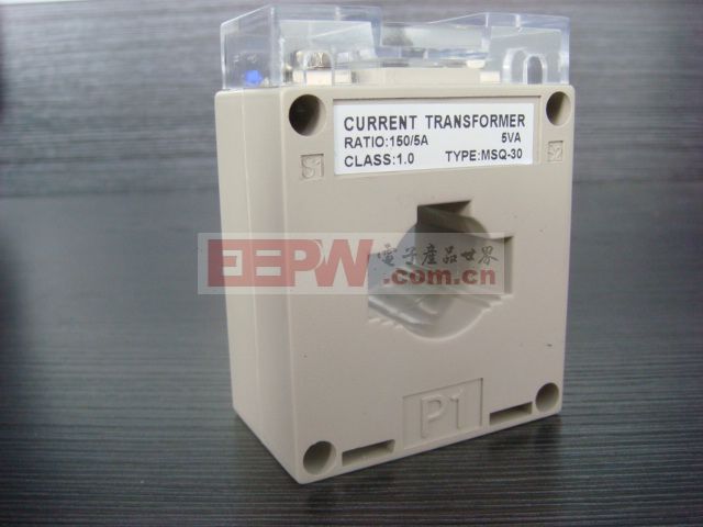
The current transformer, the English name is Current transformer, and the symbol is TA. It is a device based on the principle of electromagnetic induction for completing large current to small current conversion. It can be used for safety detection of large currents, self-protection of lines, etc., and has been widely used in our daily life.
Second, the principle of current transformers - - classification
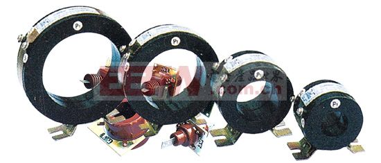
Current transformers have different classification methods according to different classification forms. They can be divided into electromagnetic current transformers and electronic current transformers according to different principles; they are divided into measurement current transformers and protection according to their different uses. Current transformers are classified into dry current transformers, cast current transformers, oil-immersed current transformers and gas-insulated current transformers according to their different dielectric materials; they are divided into through-current mutual inductance according to different installation methods. , pillar current transformers, bushing current transformers and busbar current transformers. Next we will introduce the principles of several typical current transformers.
Third, the principle of ordinary current transformer
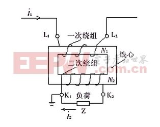
The figure below shows the schematic diagram of a common current transformer. It is mainly composed of iron core, primary and secondary windings, housing and frame. The principle of its utilization is mainly electromagnetic induction: because the primary winding is terminated. The current (ie I1 is large), and want to get a small current at the secondary winding end (ie, I2 is smaller), so N1 is smaller (ie, the number of turns in the primary winding end is smaller), and N2 is larger (ie, the secondary winding) The number of turns of the end coil is large, so that the conversion from a large current to a small current can be realized, thereby realizing the safety detection of a large current.
Fourth, the principle of through-heart current transformer
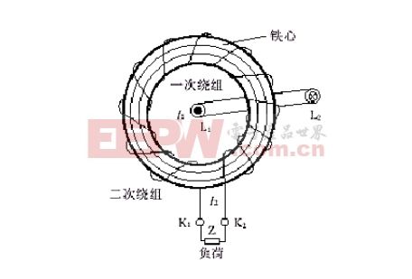
The figure below shows the schematic diagram of the through-core current transformer. The principle is the same. The difference is that it does not actually have a primary winding. It simulates the function of the primary winding by passing the current-carrying wire through the core. The secondary winding is evenly wound around the circular core. When the number of turns of the primary winding is small, N2/N1=I1/I2 becomes smaller, and conversely, when the number of turns of the primary winding is larger, it becomes larger.
Five, multi-tap current transformer principle
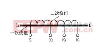
The figure below shows the schematic diagram of the multi-tap current transformer. The principle is also I1N1=I2N2, except that the secondary winding has multiple taps to achieve the function of multiple ratios. The primary winding is unchanged. When a certain ratio is needed, the corresponding secondary winding tap is taken out and used, and some secondary winding taps can also be used at the same time to facilitate comparison.
Current transformer principle related articles
T Copper Tube Terminals,Non-Insulated Pin-Shaped Naked Terminal,Copper Cable Lugs Terminals,Insulated Fork Cable Spade Terminal
Taixing Longyi Terminals Co.,Ltd. , https://www.longyiterminals.com