The ADAU1401 is a complete single-chip audio system, including a fully programmable 28 / 56-bit audio DSP, analog-to-digital converter (ADC), digital-to-analog converter (DAC), and microcontroller-like control interface. Signal processing includes equalization, bass enhancement, multi-band dynamic processing, delay compensation, speaker compensation, and stereo sound field widening. This processing technology is comparable to the effect of high-end studio equipment, and can compensate for the distortion caused by the practical limitations of speakers, power amplifiers and listening environments, thereby significantly improving the sound quality.
With the convenient and easy-to-use SigmaStudio development tool, users can use different functional modules to configure the signal processing flow graphically, such as modules such as biquad filters, dynamic processors, level control, and GPIO interface control.
Noise floor
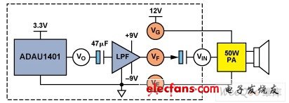
Unlike portable devices, car audio systems are equipped with high-power amplifiers, each amplifier can provide up to 40 W-50 W of power, and each car has at least four speakers. Due to the high power, the noise floor is easily amplified, so that the human ear can feel it in a quiet environment. For example, assuming a speaker sensitivity of approximately 90 dB / W, 1 mV rms noise in a 4 Ω speaker can produce a sound pressure level (SPL) of approximately 24 dB, a level of noise that human ears can perceive in a quiet environment. There are many possible noise sources. As shown in Figure 1, the main noise sources include power supply noise (VG), filter / buffer noise (VF), and noise VE caused by improper power ground layout. VO is the audio signal from the processor, and VIN is the audio input signal of the speaker power amplifier.

Figure 1. Examples of noise sources in car audio systems
Popping during power switching: Car audio power amplifiers are generally powered by a single 12 V power supply, while DSPs require a low-voltage power supply (eg 3.3 V), and the filter / buffer may be powered by dual power supplies (eg ± 9 V). Between each part of the circuit working with different power supply voltages, coupling capacitors must be used to provide signal isolation. During power on / off, the capacitor is charged / discharged at an extremely fast rate, and the resulting voltage jump propagates along the signal chain, eventually causing the speaker to make a popping sound. Figure 2 shows this process.

Figure 2. The principle of loudspeaker sound
Although the sources of noise floor and pop noise are known, and efforts are made to adopt good circuit design and layout techniques, as well as to select good devices with lower noise to reduce noise at the signal source, many uncertainties may still appear during the design process . Designers of automotive multimedia systems must deal with many complex issues, so they must possess high-level analog / mixed-signal design skills. Even so, the performance of the prototype product may still not match the original expectations. For example, a noise level of 1 mV rms poses a huge challenge. As for popping, existing solutions use MCUs to control the operating sequence of the power amplifier during power switching, but when the MCU is far from the power amplifier, layout and wiring and electromagnetic interference (EMI) can pose potential problems.
Power consumption
With the increasing number of in-vehicle electronic devices, power consumption problems have become increasingly serious. For example, if the quiescent current of an audio power amplifier reaches 200 mA, when using a 12 V power supply, the quiescent power consumption is as high as 2.4 W. If there is a way to detect that there is no input signal or the signal is small enough to turn off the power amplifier, then when the power is turned on but the speaker does not need to emit sound, it can save a lot of power consumption.
Xlpe Control Cable,Termite Resistant Control Cable,Termite Proof Control Cable,Termite Proof Xlpe Control Cable
Baosheng Science&Technology Innovation Co.,Ltd , https://www.bscables.com