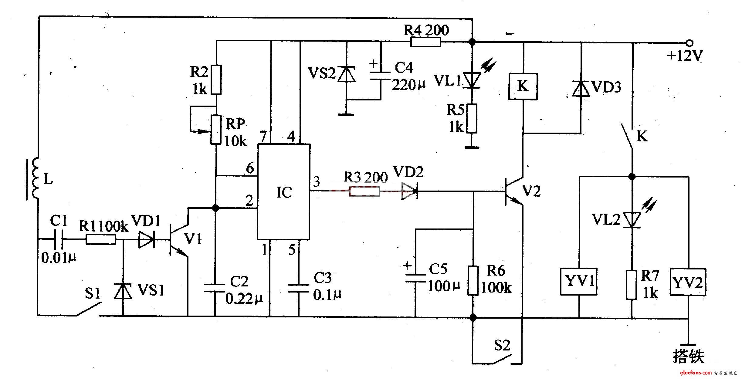
Circuit working principle
The automotive electronic fuel-saving circuit is composed of transistors Vl, V2, integrated circuit IC, Relay K, solenoid valves YVl, YV2 and related peripheral components, as shown in the figure.

Component selection
Rl-R3 and R5-R7 select 1 / 4W carbon film resistors; R4 selects lW carbon film resistors.
RP selects membrane variable resistor.
Cl-C3 uses monolithic capacitors or polyester capacitors; C4 and C5 use aluminum electrolytic capacitors with a voltage resistance of 16V.
VDl-VD3 selects 1N4001 or 1N4007 silicon rectifier diodes.
VSl selects 1 / 4W, 1? 8V voltage stabilizing diode, such as 1N4614, 2CW5O and other models; VS2 selects 1? 5W, 6? LV voltage stabilizing diode, such as 1N5920 and other models.
VLl selects green high-brightness light-emitting diodes of φ5mm; VU selects red light-emitting diodes of φ5mm.
Vl selects S9013 silicon NPN transistor; V2 selects S805O or C8050 silicon NPN transistor.
IC selects NE555 type time base integrated circuit.
In the circuit, L is the primary winding of the ignition coil on the car, and Sl is the contact switch (commonly known as "platinum") on the car distributor. S2 is the fuel saving switch, which is installed at the valve position screw and acts simultaneously with the throttle valve (When the throttle is open, S2 is turned off; when the throttle is closed, S2 is turned on).
When the car starts, the + 12V power supply is turned on, and the light-emitting diode VLl lights up. After + 12V voltage is limited by resistor R4, step-down, capacitor C4 filtering, and voltage stabilizing diode VS2, it generates an operating voltage of about + 6V. This voltage is directly supplied to the IC all the way; the other is through resistor R2 and variable resistance RP is added to the collector of V1 to charge capacitor C2. At this time, pins 2 and 6 of the IC are high, and pin 3 is low, V2 is in the cut-off state, the relay K and the solenoid valves YVl and YV2 are not working, and the oil circuit is in the oil supply working state.
When the automobile engine starts to run, due to the switching effect of Sl, a pulse voltage is generated across the coil L. This pulse voltage is processed by the DC blocking capacitor Cl, the resistor Rl, the clamping diode VSl, and the limiting diode VDl, and then applied to the base of Vl to turn on Vl, which generates a low level on pins 2 and 6 of the IC. The pulse turns the monostable flip-flop inside the IC from a steady state to a transient state, and its 3 feet change from a low level to a high level, making Ni's base extremely high.
When the car is driving, the fuel-saving switch S2 is controlled by the car driver while operating the throttle, and is generally in the off state, so V2 is cut off, K does not pull in, YVl and YV2 do not move, and the engine normally supplies fuel . When the car encounters a glide, deceleration or other situations where oil is not used, the driver can loosen the oil pedal to close S2, V2 is turned on, the relay K is closed, and the solenoid valves YVl and YV2 all act to block the oil circuit and stop Fuel is supplied to the engine while the light-emitting diode VL2 emits light.
The two solenoid valves YV1 and YV2 control the oil passage and main orifice of the carburetor, respectively. When the fuel supply is stopped, the oil level in the float chamber can be kept unchanged. After the fuel supply is stopped, the engine speed decreases accordingly, and the duty cycle of the car ignition pulse (the ratio of the pulse period to the pulse width) also decreases. small. When the charging voltage on C2 is greater than 2Vcc / 3 (above 4V) in two pulse cycles, the monostable trigger inside the IC will change from transient to steady state, and its 3 feet will be inverted from high level to low Level, V2 is cut off, K contact is released, the solenoid valves YVl and YV2 are powered off, the valve core is reset, and the carburetor resumes fuel supply to ensure that the vehicle maintains the idling state at the lowest speed or stop state; meanwhile, VL2 Turn off until it accelerates again.
Installation and commissioning
After the circuit welding is completed, remove the original oil pipe of the car carburetor float chamber, install the oil inlet control solenoid valve YVl between the oil pipe and the float chamber; then remove the main measuring hole screw and replace it with the main measuring hole Control the solenoid valve YV2, remove the throttle screw, install the special insulated screw, and adjust the idle speed again.
Pump the gasoline into the float chamber by hand to see if there is oil leakage at the connection between the two solenoid valves and the carburetor. After the inspection is correct, you can test drive:
First put the shift lever of the car into neutral position, start the engine, slowly accelerate the engine after the engine starts running, and then quickly release the accelerator pedal after it runs normally. If the VU can light up at this time, the engine speed gradually decreases , It means that S2 is closed normally, the solenoid valves YV1 and YV2 have been operated, and the oil circuit is blocked. If the engine speed drops to idle speed, VL2 goes out, it means that the solenoid valves YVI and YV2 have been reset, the fuel economizer starts to supply oil, and the engine maintains idle speed.
If VL2 shows a short time after releasing the accelerator pedal, the display time of VL2 can be increased by adjusting the resistance of variable resistor RP until VL2 goes out when the engine speed drops to idle speed.
Ac Contactor,Contactor For Ac Unit,Compressor Contactor,Air Conditioner Contactor
NanJing QUANNING electric Co.,Ltd , https://www.quanningtrading.com