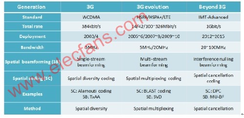
Table 1: The evolution of 3G MIMO technology applicable to the 3G standard.
Table 2 is an overview of the 3GPP LTE standard TR 25.913, which shows the performance in a single input single output (SISO) and MIMO antenna configuration at a fixed 6? QAM modulation depth. These numbers represent the physical limitations of the frequency division duplex (FDD) air interface under ideal wireless conditions (with signaling overhead compensation).

Table 2: 3G MIMO application (6? QAM) data rate performance.
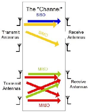
In wireless communication systems, the use of multiple antennas on the transmitter and / or receiver opens up a new dimension space. If this technology can be used correctly, it can greatly improve performance, and it is now widely known as MIMO system. Input and output here refer to wireless channels. Multiple antennas of the transmitter means that multiple signals are input into the wireless channel, and multiple antennas of the receiver means that multiple signals are output from the wireless channel. Figure 1 is a simple demonstration of SISO, SIMO, MISO and MIMO systems. Through this figure, you can easily understand that for the MIMO system of the transmitter antenna (T) and the receiver antenna (R), if the channel between each transmit and receive antenna pair independently fades, the channel diversity order is T × R.

Figure 1: The relationship between SISO, SIMO, MISO and MIMO systems.
Different MIMO applications
In a dense multipath scattering environment, the MIMO system can make full use of spatially separated antennas to obtain spatial diversity. MIMO systems can be implemented in many different ways to obtain diversity gain or capacity gain against signal fading. Generally, MIMO technology has three types. The first category aims to improve power efficiency by maximizing space diversity. Such techniques include delay diversity, space-time block coding (STBC) and space-time trellis code (STTC). The second type utilizes spatial multiplexing in a rich scattering environment to transmit independent data signals through antennas to increase the data rate, but usually cannot achieve complete spatial diversity. The third type utilizes the channel information of the transmitter, also known as beamforming. It uses the channel information to establish a beamforming matrix that acts as a pre-filter and a post-filter for the transmitter and receiver to achieve capacity gain.
Spatial diversity
The fluctuation of signal power in the wireless channel is very fast. When the signal power drops significantly, the channel is in a fading state. Diversity is used to resist fading in wireless channels. Receive antenna diversity can be used in the SIMO channel. The receiving antenna receives independent fading states of the same signal and combines with these signals, so that the amplitude variation of the composite signal is smaller than that of any antenna. The number of independent fading channels is usually used to describe the characteristics of diversity. This number is also called "diversity order", and if the same transmit antenna has independent fading characteristics for all channels of the receiving antenna, the diversity and the receiving antenna in the SIMO channel The number is equal. Transmit diversity is suitable for the MISO channel and has become a research field of great interest. Extracting diversity requires proper design of the transmitted signal. Use a suitable combination scheme on the receiver to obtain diversity gain. If all channels from the transmitting antenna to the same receiving antenna have independent fading characteristics, the diversity of the channel is equal to the number of transmitting antennas.

Figure 2: (a) AlamouTI space-time coding transmitter structure; (b) spatial multiplexing transmitter structure; (c) beamforming transmitter structure.
Figure 2 shows an example of a simple transmitter diversity scheme, also known as AlamouTI space-time coding. During the specified symbol period, the two antennas simultaneously emit two signals. In symbol period t1, signals s0 and s1 are sent from antenna 0 and antenna 1, respectively. In the next symbol period t2, antenna 0 sends signal -s1 * and antenna 1 sends signal s0 *, where () * is complex conjugate Operation. This sequence is shown in Figure 2. Coding is done in space-time coding, but also in space-frequency coding. Instead of two adjacent symbol periods, two adjacent carriers (space frequency coding) can be used. Diversity using MIMO channels requires combining transmit and receive diversity as described above. If the channel between each transmit and receive antenna pair fades independently, the diversity order is equal to the number of transmit and receive antennas.
Spatial multiplexing
Spatial multiplexing can provide a linearly increased transmission rate for signals of the same bandwidth without causing additional power loss.
Figure 2 (a) shows a simple spatial multiplexing system with two transmit antennas. This concept can be extended to more general MIMO systems. The transmitted bit stream is demultiplexed into two sub-bit streams with half the rate, which are modulated and transmitted simultaneously by each transmitting antenna. For example, in FIG. 2 (a), in symbol period t1, antenna 0 transmits symbol s0, and antenna 1 transmits symbol s1. During symbol period t2, antenna 0 transmits symbol s2 and antenna 1 transmits symbol s3. Therefore, the transmission rate is twice that of the SISO system. Under the best channel conditions, the spatial characteristics of the signal received by the receiver can be well separated. The receiver can distinguish and extract two co-channel signals based on the channel information. After demodulation, the sub-bit streams can be combined with each other to generate the original bit stream. Therefore, the transmission rate that can be improved by spatial multiplexing is proportional to the number of transmit and receive antenna pairs. Spatial multiplexing can also be used for multi-user formats, that is, space division multiple access or SDMA. Suppose that two users transmit independent signals, and both signals arrive at a base station equipped with two antennas. The base station can separate the two signals to support two users using the channel at the same time. This enables the capacity to increase in proportion to the number of base station antennas and the number of users.
Beamforming
In spatial diversity and spatial multiplexing, it is generally assumed that the transmitter does not know the channel information. When the transmitter has channel information, it can improve system performance. The channel information can be complete or partial. Complete channel information means that the transmitter knows the channel matrix. Part of the information may refer to certain parameters of the instantaneous channel (such as the condition number of the matrix channel) or statistical characteristics (such as the relevant characteristics of transmission or reception). Figure 2 (b) shows the precoding framework using channel information. The transmitted signals (S0, S1) are multiplied by the precoding, which can be interpreted as beamforming. After precoding, the two separate data streams can be sent simultaneously from the two transmit antennas as spatial multiplexing, but the matrix encoder will change according to the channel information. Assuming that the transmitter already knows the transmission correlation matrix, the feature matrix of the correlation matrix can be used to establish a precoding matrix to optimize the traversal capacity. Representing the 2 × 2 precoding matrix as W, the transmitted symbol in symbol period t1 is:

Similarly, the precoding matrix can be used to represent the transmitted symbols x2 and x3. In this precoding scheme, the transmission rate is proportional to the number of transmit and receive antenna pairs.
Channel dependence of MIMO performance
For wireless communication systems, the channel is the key factor, which determines the performance of the system. For example, loss and fading can cause signal amplitude attenuation, and multipath can cause inter-symbol interference. Although MIMO opens up a new dimension space that can greatly improve performance, whether diversity or capacity gain can be achieved depends on the channel characteristics. In STBC applications, whether the diversity gain can be achieved depends on the channel diversity order. Only when there is an independent fading channel between each transmit and receive antenna pair, the channel diversity order is equal to the number of transmit and receive antennas. This means that if the channel between the pair of transmit and receive antennas has a high correlation characteristic, the diversity gain that can be obtained will be very limited. Spatial multiplexing applications also require channel independent characteristics. Only under the optimal channel conditions, the different spatial signal streams can be well separated, which means that the channels between the pair of transmitting and receiving antennas have low correlation characteristics.
Challenges in MIMO performance testing
With the increase of MIMO system transmitter / receiver units, the complexity of product design and development is also rapidly increasing, which also brings challenges to MIMO performance testing. As mentioned above, the performance of MIMO depends on the channel. In order to study the receiver performance under different channel conditions, the MIMO channel must be used. In the early design and verification cycle, testing directly in the real wireless channel environment is not an effective method. This is very time-consuming, and due to the channel sensitivity and changeability, it is very difficult to repeatedly generate research questions. Using software to generate channel coefficients is another option, but it is not ideal. Because the transmission signal coefficient generation and convolution calculation process is extremely time-consuming and resource-intensive, it is not feasible to use only software to simulate channel behavior in real-time testing. In addition, the channel model becomes more and more complex, and different communication standards require the use of different channel models and test environments. Repeatedly generating all these channel models and test environments will increase the burden on design engineers, and time-consuming testing will slow down the fault diagnosis process and development cycle. Therefore, a professional MIMO channel emulator is a key tool for these engineers to speed up the work process.
The MIMO channel emulator uses powerful digital signal processing technology to repeatedly generate a set, real-world channel environment, which enables engineers to isolate performance problems during early deployment and design verification stages and provides comprehensive fault diagnosis of components or systems The fastest method. The current SISO channel emulator cannot effectively solve the problem of MIMO performance testing. First, each receiver needs to sum the signal streams of different transmitters; second, the multi-level parallel SISO channel simulator cannot simulate the relevant characteristics of different channels, which is an important feature of the MIMO channel; third, Meeting the required number of channels is a huge challenge for the SISO channel emulator.
Professional instruments that can simulate real MIMO channels provide the best solution for these complex test conditions. Channel emulators (such as the N5106A PXB MIMO receiver tester) use powerful digital processing techniques to repeatedly generate real MIMO conditions, enabling rapid isolation of performance issues early in the design, deployment, and verification cycle. The channel emulator also has the advantage that it can generate real fading environments, including path and channel correlation, with lower implementation costs and faster calibration processes.

Figure 3. The Agilent N5106A MIMO receiver tester can provide up to 4 baseband generators and 8 faders, which helps to test and troubleshoot systems up to 4 × 2 MIMO. Agilent Signal Studio signal generation software runs on this tester and provides engineers with the latest standard conformance signal generation functions.
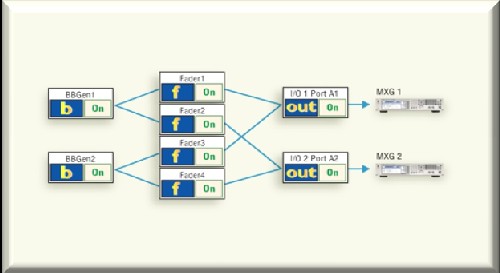
Figure 4 shows a simplified configuration diagram for testing a 2 × 2 MIMO receiver. The measuring instrument is connected to two radio frequency signal generators for signal up-conversion, and the internal baseband generator of the instrument generates standard conformance waveforms, such as LTE signals. Through the graphical interface of the software, the user can clearly see the correspondence between the baseband generator and the channel fader. Each fader can be independently configured using a standard consistent fading model, such as using 3GPP LTE standard 36.101 Annex B, or using various paths and fading conditions to customize a configurable model. Unlike an independent fader, the instrument's automatic power calibration function eliminates the boring and time-consuming system settings required for fading.

Figure 4: Simplified block diagram of an Agilent N5106A PXB MIMO receiver tester for testing a 2 × 2 MIMO receiver.
Summary of this article
This article outlines the MIMO technology in advanced 3G / 4G wireless communication systems, introduces the basic concepts of spatial diversity, spatial multiplexing, and beamforming and their impact on MIMO performance. When used in a rich multipath environment, MIMO technology has the potential to improve the robustness of the signal and expand the capacity. The development and testing of MIMO components and systems requires the use of advanced channel simulation tools that can be easily configured and provide accurate characterization of real wireless channels and conditions. This article also shared with readers how to use commercially available instruments (such as Agilent N5106A PXB MIMO receiver tester) to simulate these complex channels.
Fiber Optic Accessories,Fiber Optic Cable Connectors,Fiber Optic Adapter,Fiber Cable Connectors
Huizhou Fibercan Industrial Co.Ltd , https://www.fibercaniot.com