Automobile informationization and intelligence are the focus of today's automotive research, and have become an important indicator to measure the development level of automobile industry in various countries [1]. As a new automobile concept and automobile product, smart car will become the mainstream of automobile production and automobile market. Product [2]. The "Freescale" Cup National College Student Smart Car Competition is sponsored by the Higher Education Automation Teaching Guidance Subcommittee, co-organized by Freescale Semiconductor, and organized by the universities in each division. The game is based on the rapid development of automotive electronics, covering the scientific and technological creativity of control, pattern recognition, sensing technology, electronics, electrical, computer, mechanical and other disciplines. It aims to cultivate students' ability to grasp and innovate knowledge. And the ability to engage in scientific research [3].
This article refers to the address: http://
According to the "Freescale" smart car competition rules: using a unified car model, the core control unit uses Freescale MC9S12DG128CPU. On this basis, the design of the control scheme and system control circuit is designed. The system control circuit design includes: sensor signal acquisition, processing circuit design, drive motor and steering servo control circuit design and various interface circuit design. The control scheme design includes: the design of the control system, the design and optimization of various algorithms. After the system design and commissioning is completed, the self-tracking walk is completed on the specified track marked with the guide line. The track is to lay a black guide line on the white bottom plate, so that the shortest time is the winner. The competition is divided into a photoelectric group and a camera group. The author is the camera group, which uses the camera tracking method.
The control system of the smart car (hereinafter referred to as the car) is mainly composed of three parts: sensor signal acquisition and processing, vehicle speed control and steering control. The road information is collected by the camera, and the path is identified after processing and analysis, and different speeds and steering angles are determined according to different paths [4-5]. On the basis of ensuring safety, on the one hand, we need to consider how to increase the limit speed. On the other hand, we need to consider how to increase the average speed. The average speed will ultimately determine the performance of the game. Analysis of previous competitions can be found that 60% to 70% of the length of the track is a curve. Therefore, the speed of the curve of the car largely determines the average speed of the car on the entire track. This article will focus on how to use the image data to give a reasonable steering strategy for the car during the walking process.
As far as the average driver is concerned, the driving vehicle is on the road, and maintains a high-speed operation when the road is straight, and makes a reasonable decision according to different curves when cornering. Generally, the first speed is decelerated, then the curve is passed at a relatively low speed, accelerated after cornering, and finally returned to the straight speed. The situation on the race track is different. It is easy for the racer to choose the turning strategy of the ordinary driver. Instead, he uses the centripetal force of the front wheel steering and combines the inherent inertia of the car before entering the corner to achieve a fast turn. Can a smart car with vision also simulate this high-speed movement to win the game? After comprehensively analyzing the characteristics of the visual image, the steering gear model and the characteristics of the circular motion, the author proposes a safe cornering strategy that can enter the curve at high speed without deceleration or slight deceleration, while ensuring that the car will not rush out of the track.
1 Road information extraction
To realize a complete visual tracing-based smart car, first use the camera to obtain road information, and then perform data processing on the collected original image to obtain the position of the guide line in the image coordinate system on the track [6-8] .
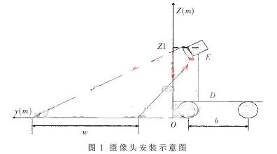
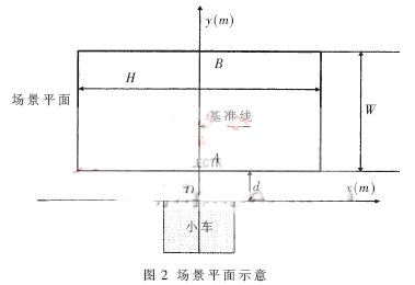
Figure 1 is a schematic view of the camera installation. Where Z1 is the height of the camera from the ground; w is the width of the field of view scene, and its size is related to the depression angle and height of the camera installation; b is the wheel spacing. For a feature point in a scene, as long as it knows its position in the scene, the relative position of the point to the cart can be calculated. Looking from the top to the bottom of the Z axis in the opposite direction, you can get the scene plane, as shown in Figure 2. The distance between the scene plane and the trolley is d, and the distance is a blind zone. The plane width of the scene is W and the length is H. Define the center line of the car as the baseline, and the image obtained by the camera is the scene plane. Due to the limitation of the processing capability of the MC9S12DG128CPU, the 356×292 CMOS black and white camera is selected and set to the progressive scan mode. Sampling 106 points in a single line. According to the experimental results, considering various factors, 64 rows of information are selected to form a 64×106 image plane, which is used to judge the position of the curve, the straight road and the curve, so as to reduce the calculation amount. The image is shown in Figure 3.
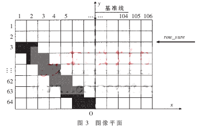
On the basis of the image plane of Fig. 3, the position of the guide line is extracted line by line by the method in References [9-10]. Mark the line without the guide line and mark the boundary line without the guide line as row_sure. This value records that there are no guide lines from the first line in the 64 lines of data, which is simply called the outbound point. The position of the guide line in the image is obtained, and the rotation angle of the steering gear can be controlled according to the image coordinates of the guide line. The image coordinates of the single-line image data are linearly transformed with the corresponding real scene coordinates, that is, the column difference of any two pixel coordinates of each row is multiplied by an approximately fixed proportional coefficient K to obtain the difference of the corresponding scene coordinates of the real scene:
ΔXworld=K×ΔXimage=K×(line2-line1) (1)
Where ΔXworld is the distance between two points in the real scene coordinates, and ΔXimage is the column difference of the pixel coordinates of the two points on the corresponding line of the image plane.
Using the above relationship, the declination between the trolley and the target guide line can be indirectly measured, as shown in FIG. If AB is the reference line, that is, the center line of the car; AK is the guide line; the point F is perpendicular to the y-axis, the intersection with the reference line AB is C, and the point C is defined as the reference position. In the triangular AFC, the angle β is the angle between the reference line and the guide line:
![]()
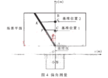
In an ideal situation, controlling the steering gear to deflect the β angle to the left allows the car to follow the guide line. However, the calculation burden of the calculation angle is very heavy, and the measurement method of the lateral deviation in the reference [2] is simplified. In the case where the reference position is fixed, the length of the CF can be approximated by the length of the angle β:
|CF|=K×β (3)
Where K is a scale factor. Combining the relationship between the image plane and the scene plane, the length of the CF is defined as the deviation, and the image plane is converted to:
Err=line1-linem (4)
In the formula, linem is the column value corresponding to the reference position, line1 is the column value of the peer guide line, and err is the position deviation. Therefore, in the actual software design, it is not necessary to obtain the real scene coordinates, and the control algorithm can be directly designed for the difference of the image coordinates between the actual position of the guide line and the reference position (line1-linem). For example, the incremental PID controller can be designed as:
Δu(k)=u(k)-u(k-1)=KP[err(k)-err(k-1)]+KIerr(k)+KD[err(k)-2err(k-1) +err(k-2)]
In the formula, KP is a proportional coefficient, KI is an integral coefficient, and KD is a differential coefficient. Δu is the given increment of the servo [7-11].
2 steering model
Obtain the position information of the road, that is, obtain the steering angle of the car at the moment. According to the steering gear steering model in [11], in the ideal state, at this moment, the steering gear is controlled to deflect the front wheel to the corresponding angle to realize the follow-up of the trolley. The steering of the steering gear is equivalent to giving the car a centripetal force. When the corner is constant, the car makes a circular motion. If the PWM pulse width of the control motor is constant, the car makes a uniform circular motion, and the PWM pulse width corresponding to the driving motor corresponds to the car speed. It is equivalent to the linear velocity of a uniform circular motion. As shown in Fig. 5, the side track of the vehicle is b, the steering angle of the steering gear is θ, O is the center of the circular motion of the vehicle, and R is the radius corresponding to the outer wheel. The radius of each corner corresponds to the circular motion [2] is as follows :
![]()
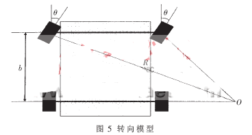
Let the control period be T, the current speed of the trolley is V, and α is the number of arcs of the trolley traveling along the circumference within one control period T, then:

It can be seen from the above model that different speeds and rotation angles will have different radians in one control period T, and discretization of the above formula can be obtained:
![]()
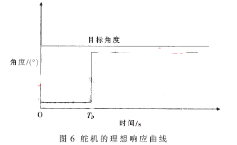
During the turning process, the steering angle of the steering gear is limited by various factors (such as the delay of the steering caused by the steering mechanism of the trolley, the time constant of the steering gear, etc.), which is a gradual process, and is calculated by the formula (8). The premise is that the direction of the steering gear can be changed immediately as the amount of control changes. In order to simplify the analysis, the steering gear model is regarded as a delay only with a delay time TD and its time constant is ignored. As shown in FIG. 6, due to the presence of the TD, the speed is larger, and the distance the trolley travels is longer in the lag time TD.
3 steering strategy design
As shown in Fig. 7, it is assumed that the distance D in front of the trolley is a curve, and the speed of the trolley is V at the moment. In combination with the steering curve of the ideal steering of the steering gear of Fig. 6, if the trolley enters the corner at point A, the speed must satisfy:
D=V×TD (9)
In FIG. 4, for the reference position 1 and the reference position 2, as a result of the road information extraction, in order to ensure that the point A is bent, the reference position 2 issues a steering command earlier than the reference position 1, and a greater speed is required. A point into the corner, under the premise that the speed of the two positions can be safely bent, the reference position 2 gets a higher inflection speed, so getting the information of the curve earlier can increase the bending speed. At the same time, if the car wants to enter the curve quickly, the reference position must be referred to a position matching the speed at that moment to cancel the additional driving path caused by the servo delay. But it's not that you can get a big cornering speed by selecting the reference position far enough. The answer is no. The steering of the trolley is an approximate circular motion, and the different speeds obviously correspond to different driving radii, ie different paths. When the speed is fast, the radius is large; when the speed is slow, the radius is small. Too fast speed will make the car out of the track. The curve of the competition track is mainly composed of 360°, 180°, 90° and S-type tracks. In the 180° curve shown in Fig. 8, the middle thick solid line is the guide line, the outermost solid line is the track boundary, and the curves 1, 2, 3, and 4 are the trolley travel routes. It is assumed that all driving routes have the same bending angle, curves 1, 2, and 3 are B points and the speed is different; curve 4 is the E point entering the curve, and the speed is consistent with the curve 3 speed.
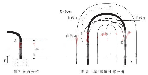
Obviously, the curve 3 in the curves 1, 2, and 3 has the fastest speed, but the path is the longest, and there is also the danger of rushing out of the track; although the curve 2 is “cut near the roadâ€, the speed is slightly slower; the curve 1 is too slow. Slow and unable to bend. It is not difficult to see that the curves of curves 2, 3, and 4 are not very different. However, in curve 2, it is necessary to decelerate when entering the bend by straight AB, and it is necessary to accelerate after cornering, which is longer than curves 3 and 4. After comprehensive consideration, curves 3 and 4 have the shortest turning time. Curve 3 in curves 3 and 4 clearly has the danger of rushing out of the track, so curve 4 is the optimal path for a 180° bend. It can be seen that early advancement at high speed allows the car to drive through the curve at a relatively high speed while ensuring safety without rushing out of the track.
For a 90° curve, similar to 180°, the optimal strategy is to maintain a straight track at a high speed and ensure a safe cornering through the above-mentioned early entry strategy.
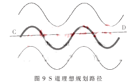
For the entry of the S road, it can be analogized. For the S-way driving, the vehicle speed should be appropriately lowered and the reference position should be appropriately lowered. As shown in Figure 9, the shortest path is also the fastest, and the two are unified. It is very difficult to get the car to take the CD route in the real process, but if you can keep the steering gear in a small angle adjustment process, you can approach the CD route. Practice has proved that avoiding severe angular changes when passing through the S-channel at high speed is given as the optimal strategy.
Based on the above analysis, the following two conclusions can be obtained:
(1) The distance between the reference position and the trolley is proportional to the speed. In order to not decelerate into the bend, the reference position must be changed so that it can satisfy the formula (9).
(2) Speed ​​is proportional to the turning radius. Keeping the high speed into the corner without rushing out of the track, the early entry strategy can effectively solve this problem.
4 Strategy implementation
From the above analysis, the reference position in the scene can be approximated as a bend point, and different speeds will result in different entry points and different bend paths. Therefore, the control tasks to be completed are: high-speed cornering, no deceleration before entering the corner, in order to prevent the tunnel from entering the corner. It can be seen that the reference position needs to be further advanced on the basis of the inflection point adapted to the speed, that is, the distance between the reference position and the front end of the trolley is:
L=V×TD+V×τ (10)
Where L is the distance from the reference position to the cart, V is the speed of the cart for this moment, V×TD is the additional travel distance due to the offset delay time, and V×τ is the distance to advance the bend point.
It can be seen that the distance between the reference position and the trolley is a variable related to the speed of the trolley, and different speeds require different values. The reference position is set according to formula (10) for different speeds, so that high-speed cornering can be achieved. In order to obtain a better inflection point, this strategy further processes the image plane (64×106). For the obtained image plane (64×106), the image plane is divided into 10 regions, and each region is obtained. Take the average position of the guide line and replace it with an impossible value for the area without the guide line. This will simplify the guide line information into 10 lines of information, which are: average[i], i=1, 2,..., 10. Among them, average[i] records the column coordinate value of the average position of the guide line in each line of information, and the i mark indicates the line value. Figure 10 shows the final image plane.
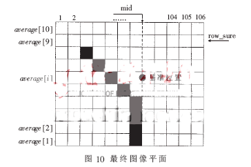
In Figure 10, row_sure is used to select which of the 10 points are available. Average[1] is the closest point to the car, and the farther away from the car as the serial number increases. In the image plane of Figure 10, the calculated deviation is changed to:
Err=average[i]-mid (11)
Where i< P>
When the speed of the car is very high, select the point farther away to obtain the deviation, which is equivalent to entering the curve ahead of time. In this way, from the above strategy analysis, as long as the bend point is appropriate, the curve can be directly entered without deceleration, and a good safety factor can be obtained. When the speed is at a lower level, you can use the nearest point, average[1], so that the car will only turn when it goes to the corner, and will not enter the corner in advance, avoiding the punching out of the corner. Inner road.
5 Experimental data
According to the requirements of the competition, the minimum arc radius in the track is not less than 0.5 m. Based on the previous track, the author designed the test track as shown in Figure 11, with a total length of about 38 m. The laboratory test score was 18 s full and the average speed reached 2 m/s.
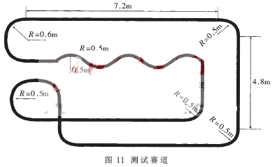
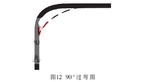
Figure 12 is a 90° curve over bend, the thick solid line is the guide line, and the dotted line is the actual driving route of the car. It can be seen that the trolley realizes the advance bend, which is a better path and effectively saves time.
The measurement of the cornering speed is sent back to the encoder by the wireless module every 40 ms. The speed is accelerated by the straight channel and then the curve is obtained as shown in Table 1.

The change of speed can be clearly seen from Table 1, where 62 is the bending speed, the standard speed is 2.4 m/s, the curve speed is 40, and the standard speed is 1.5 m/s. This speed is close to the average speed. .
Figure 13 is a 360° curve over bend, the thick solid line is the guide line, and the dotted line is the actual travel route of the car. It can be seen that the advance bend is realized, and the second half is limited by the maximum deflection angle of the steering gear. It is impossible to continue to increase the deflection, resulting in some running outer lanes.
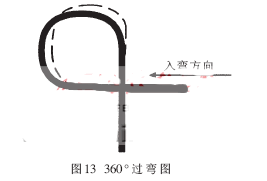
Fig. 14 is a S-bending diagram, the thick solid line is the guide line, and the broken line is the actual driving route of the trolley. It can be seen that the trolley travel route is already close to the straight road. The wireless module sends back the speed pulse measured by the encoder every 40 ms, and then accelerates from the straight lane and then enters the curve to obtain the data as shown in Table 2.


It can be seen that the speed of the S-channel changes little, and the mean corner speed is above 1.5 m/s, which is close to the expected route.
According to the steering model, by analyzing the relationship between the curved path and the bending speed, the conclusions of different speeds corresponding to different in-bending paths and in-bending points are obtained. Using this conclusion, the controller deviation calculation is changed, and the bending point is dynamically set, the curve is quickly entered, and the speed is not decelerated or decelerated as much as possible, and the driving time of the curve is shortened, thereby improving the traveling speed of the trolley. This method is equally applicable in systems where other smart cars follow the guide line, and because of its good predictive performance, it can be well followed for short guide line losses.
Outdoor Power Supply(300W 530Wh)
Outdoor power supply, also known as portable energy storage battery, is a device that uses high energy density lithium-ion battery pack as a means of energy storage to provide power supply for users when they are unable to access power. Outdoor power supply can provide power support for almost all electrical equipment. It has larger capacity, supports 220V AC output, USB fast charging output, vehicle cigarette lighter output port, DC output port, lighting flashlight, and even wireless charger and other functions, so as to provide users with more ways of power security as far as possible.
energy storage, power supply, lithium-ion battery, portable lithium battery, DC AC output
Wolong Electric Group Zhejiang Dengta Power Source Co.,Ltd , https://www.wldtbattery.com