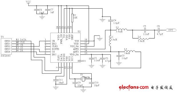
The communication frequency is the 2.4GHz ISM frequency band. Due to its advantages of license-free, shorter wavelength, small antenna size, and fewer peripheral devices, it is suitable for short-range wireless communication. The combination of ARM9 and nRF24E1 can reduce the size of the device, reduce system power consumption, and reduce the difficulty of connecting devices. According to the characteristics of ARM9 chip S3C2440, the interface circuit and driver for nFR24E1 are designed. For a small space, a system with data sharing requirements between devices is an effective solution.
The use of 2.4GHz wireless devices eliminates the trouble of connecting between systems. On the one hand, the cost of the equipment can be reduced, and on the other hand, the installation of the equipment can be simplified.
Especially for the real-time measurement of some moving parts, with the help of two wireless transmission devices, part of the measurement device can be implemented on the moving part, and the other part is installed nearby, and the real-time data of the moving part can be transmitted out for designers to Detailed analysis and improvement of real-time performance. This article focuses on the hardware connection between nRF24E1 and S3C2440 and the driver design under Linux operating system. The wireless device adopts the chip based on NF2401AG.
1 Hardware structure
nFR2401A is a single-chip 2.4GHz wireless transmission chip from Nordic. The chip consists of a fully integrated frequency synthesizer, a power amplifier, crystal oscillator and modulator. The output power and frequency can be programmed through the 3-wire interface.
1.1 Communication protocol and working mode of nFR2401
The wireless transmission and reception between nFR2401 is sent and received in the form of data packets. The data packet format is as follows:
![]()
Among them, the front buffer is automatically added by hardware, and the address is set by the user. 32 ~ 40 bits; cyclic redundancy check is automatically added by the built-in CRC error correction hardware circuit. Can be set to 0, 8, or 6 digits. The total length of all data is 256 bits.
There are four working modes of nFR2401: configuration mode, working mode, standby mode and power-down mode. The mode is set by the main control chip through software. After the chip is powered on, the S3C2440 sends the configuration data to the chip through the interface to set the transceiver mode, transceiver frequency, receive address, transmit power, CRC checksum length, valid data length, etc. During transmission, only the data packets with matching addresses and checksums can be further processed, and an interrupt signal is generated. At this time, S3C2440 reads the data. At the same time, nFR2401 can only be in one of the receiving and sending modes, and the receiving mode is generally the standby state.
1.2 Interface design between nFR2401 and S3C2440
The interface design of nFR2401 and S3C2440 is shown in Figure 1. By connecting the GPD port of the S3C2440 chip to nFR2401. The GPD port of S3C2440 is a multi-function port, which is mainly the interface of LCD screen. Since the system has no display part, this port is used as the nFR2401 interface. When the system is working, wireless communication is always working, so connect the PWR_UP pin directly to VDD. The system uses channel 1. S3C2440 adopts the query mode for nFR2401. After receiving the work command of the host computer, as long as the DR1 of nFR2401 indicates that the data is received, S3C2440 reads the data through CS, CE, DATA, CLK and stores it in the form of a file , And then send the data to the host computer through the network.

Figure 1 System block diagram.
2 Software design
The system uses Linux as the operating system. Using the S3C2440 as the platform to use the Linux operating system, there are several steps such as U-boot transplantation, Linux migration, file system compilation and programming. U-boot is used to initialize and detect basic hardware, load the boot kernel and start the file system. After downloading U-boot-1.1.1, add and modify related files. Configure its operating environment on the S3C2440 core board, and then compile to get u-boot.bin and kernel image encapsulation tool tools / mkimage. Boot program boot.bin, U-boot image u-boot.ing and its gzip compressed file u-boot .gz The complete bootloader composed of three files. The kernel settings are mainly cut and added, cut unused drivers and peripherals, and add the required drivers.
Programming under Linux operating system is divided into user layer and driver layer. The user layer is the application. The application is responsible for storing and sending data; the driver is responsible for operating the nFR2401 connection pins. The application program and the driver are connected through the library and the kernel to solve the data transmission and sharing.
new smart watch,sport smart watch,smart watch supplies,phone smart watch for Iphone
Shenzhen Konchang Electronic Technology Co.,Ltd , https://www.konchangs.com