A hot topic of discussion about single-supply op amps is whether they can do rail-to-rail input or output operations. Vendors of single-supply op amps claim their own rails have rail-to-rail input capability, but chip designers must make some tradeoffs to achieve this type of performance.

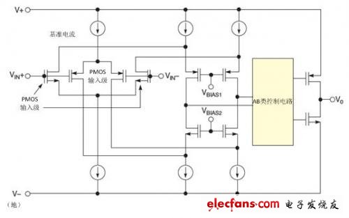
Figure 1. The combined input stage of this op amp uses PMOS and NMOS differential pairs, so the input voltage range can range from positive voltage rails to negative voltage rails.
The input structure of a typical single-supply amplifier is a parallel PMOS and NMOS differential input stage that combines the advantages of these stages to achieve true rail-to-rail input operation (Figure 1). When VIN+ is close to the negative rail, the PMOS transistor is fully turned on and the NMOS transistor is completely turned off. When the input is close to the positive voltage rail, the NMOS transistor is used and the PMOS transistor is turned off.
Although the input stage of the low-power precision op amp OPA344 in Figure 1 can operate from rail-to-rail inputs, circuit designers must address performance tradeoffs. According to the design structure in Figure 1, the offset voltage has a wide range of variation in the common-mode input range of the amplifier. In the near-ground region, the input stage PMOS offset error component dominates. In the area close to the positive power rail, it is mainly the NMOS offset error.

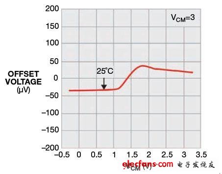
Figure 2 Since the common-mode voltage of the amplifier changes from ground to positive, the input stage of the CMOS amplifier changes completely from its PMOS input pair to its NMOS input pair when it is about 2V below the 3V positive supply rail.
The best way to see the performance of the input stage is to look at the relationship between the offset voltage and the common-mode input voltage (Figure 2). The 4.6 MHz rail-to-rail input/output CMOS amplifier LMP7701 in Figure 2 exhibits a crossover characteristic of offset voltage error at approximately 1.4V. At lower common mode input voltages, the PMOS transistor operates and the NMOS transistor turns off. At approximately 1.1V, the NMOS transistor begins to conduct. As the common mode input voltage increases, the NMOS portion of the circuit eventually takes over and the PMOS transistor is completely turned off. From 1.1V to 2V, both PMOS and NMOS transistors are operating.
To minimize the cross-effect of this input stage, there are some circuit design techniques; see the "rail-to-rail input amplifier application solution".
Single-supply amplifier manufacturers also call themselves devices with rail-to-rail swings at the output. In fact, for these types of amplifiers, the output can't be fully placed on the rail, just close.
Educational projectors are mainly aimed at classroom teaching by school teachers; traditional projectors are not easy to carry. Due to the naughty students in school classrooms, projectors are not safe to place in classrooms and are easily damaged by students. The portability of educational micro-projectors makes up for teaching Vacancy, it is convenient for teachers to give lectures and only need to store the materials in the projector and show them to students for teaching, saving the trouble of textbooks and handwriting with pens and chalks. Its general weight will not exceed 0.2Kg, and some do not even need fan cooling or ultra-small silent fan cooling.
Educational projectors need to have:
1. Clear handwriting Educational projectors most often display text and images, at least a resolution of 1024*768 or more, and a contrast ratio of more than 3000 lumens, so that students in the back row can see the projection clearly
2. Short-focus large screen;
3. Accurate color;
4. Easy operation;
5. Features such as multiple connection methods.
education projector,education use projector,smart education projector,best education projectors,projector for education
Shenzhen Happybate Trading Co.,LTD , https://www.happybateprojectors.com