1 Working principle More than 80% of the image resources on the Internet today are downloaded in RMVB format. The songs are mainly in MP3 and WMA formats, and the pictures are mainly JPG. The above-mentioned audio and video resources are mass-stored by moving media to form a “home theaterâ€. Then plug into the system via USB or SD/MMC/MS interface, the system can switch between AM/FM radio function, audio and video function and system setting through buttons or touch screen. After selecting the radio function, the AM/FM radio module starts working and is controlled by the main microprocessor. It has the functions of radio channel switching, automatic search, semi-automatic search, etc. After selecting the audio and video function, the audio and video files can be stored. The SD/MMC/MS card, U disk or USB mobile hard disk is inserted into the system, and the files in the removable medium are read by the USB HOST of the microprocessor. The file can support formats such as FAT/FAT32/NTFS, and the system selects RMVB and MP3. Hardware decoding is performed in different formats such as JPG, and the decoded video signal is transmitted to the liquid crystal display through YPrPb or CVBS format. After decoding, the audio signal is a weak signal, which is connected to the car audio through the audio amplifier.
This article refers to the address: http://
2 overall design The overall design block diagram of the system is shown in Figure 1.

The microprocessor chip uses Amlogic's AML8613. It is a sound/video dedicated processor. Its main functions are: video, audio decoding, peripheral storage medium reading and processing, touch screen data processing, radio control processing, analog display driver chip operation processing, button and remote control infrared receiving processing. . The AM/FM radio module uses Si4730 from Silicon Labs. It mainly completes AM and FM radio broadcasts, as well as search and storage functions.
In order to better watch the video images, the system uses a low-cost yuan 7" analog screen. The analog display driver chip uses Taiwan's Terawins T108L. It uses the I2C communication interface, which can be initialized and controlled by the AML8613.
The 4-wire resistive touch screen sampling chip uses TSC2003, which communicates with the microprocessor through the I2C bus. The audio multiplexer is used to select whether the currently playing sound is a radio or RMVB format. The system uses ST company's TDA7418, and its communication interface is also an I2C communication bus, which can be directly connected to the I2C bus for communication. The car audio power amplifier uses ST's TDA7384, which has low distortion, low output noise, and 4 35 W power amplifiers to directly drive the interior speakers. An external 32 Mb SPI Flash is used to store the embedded operating system, user program code, and interface images. The SDRAM function is to increase the program running speed by inserting the embedded operating system and the user program bootloader in the SPI Flash into the SDRAM after the system is booted.
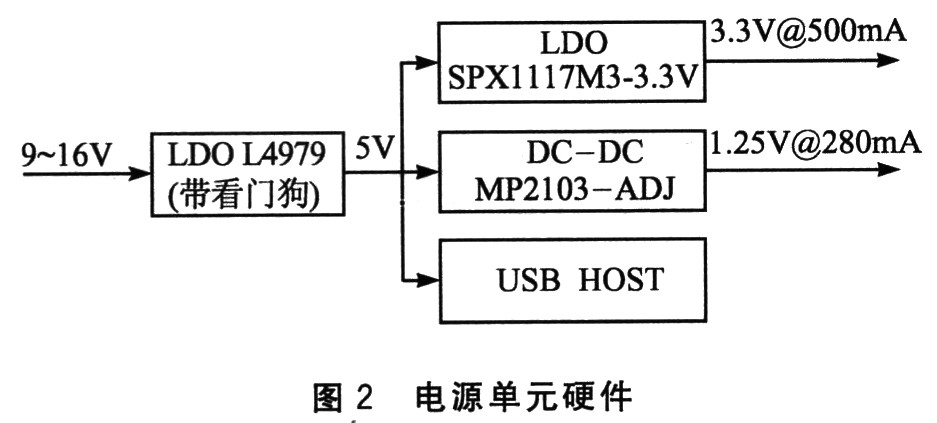
Hardware Design 3 (1) requires power processing unit AML8613 3.3 V, 1.25 V power supply, USB HOST interface unit requires 5 V power supply. Other chip power requirements are 5 V and 3.3 V. The car's power supply range is generally 9 to 16 V. This requires converting the vehicle power supply to the above three power sources to power the chip. L4979-vehicle power supply through the first converted into 5 V, and then were treated with MP2103 SPX1117M3-3.3 V and 3.3 V and converted into 1.25 V. The hardware design is shown in Figure 2.
Due to the large number of in-vehicle interference factors (such as engine, ignition system, wiper drive motor and relay), the most threatening interference is mostly common mode interference, and a small part also has differential mode interference, so the system needs to add a total of power input The mode/differential mode interferes with the filter circuit, and increases the capacity and inductance of the aluminum electrolytic capacitor, and adds a TVS tube to eliminate the interference at the input end of the vehicle power supply.
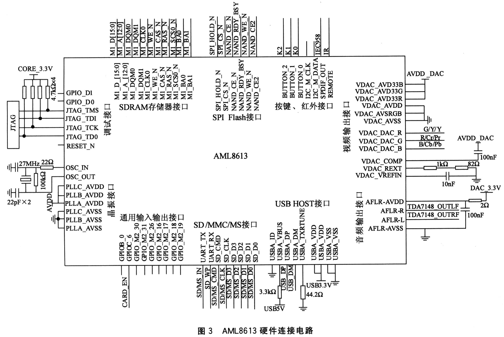
(2) AML8613 interface unit of the main control chip AML8613 is the main control chip of the system, which is responsible for the cooperation between each sub-module, and also integrates the video/audio decoding hardware engine. It can be seen that this chip is the core chip of the system, and its design determines the function and reliability of the system. Its external hardware interface circuit is shown in Figure 3. It is divided into SPIFlash, SDRAM, KEY, infrared receiving, debugging interface, SD/MMC/MS, LISB HOST, audio output, video output and other modules.
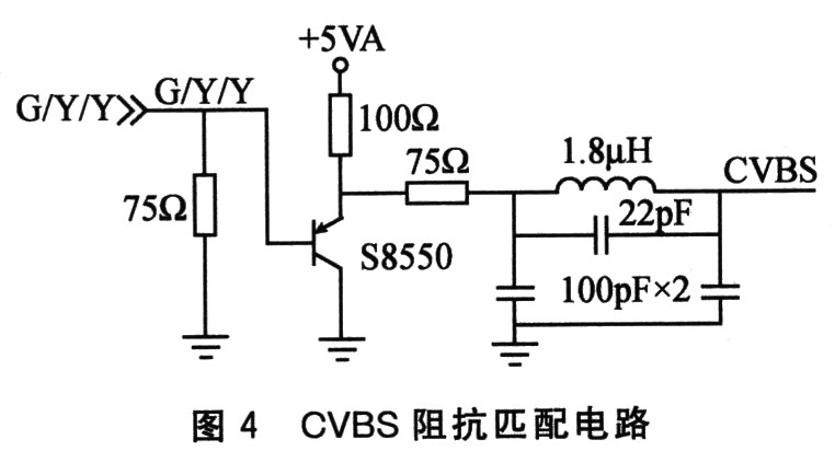
(3) Audio and video processing unit The video signal output from the AML8613 is connected to the analog display driver, and impedance matching is required between them to avoid loss of video signal. The matching circuit uses a π-type circuit to match the output impedance and the input impedance. The CVBS signal is output from the AML8613 pin G/Y/Y through the matching circuit shown in FIG.
The YPbPr video impedance matching circuit is also similar to the circuit shown in FIG. The matching circuit uses a π-type circuit. The YPbPr corresponding pin VDAC_DAC_G/VDAC_DAC_R/VDAC_DAC_B of the AML8613 is impedance matched and outputs the YPbPr signal.
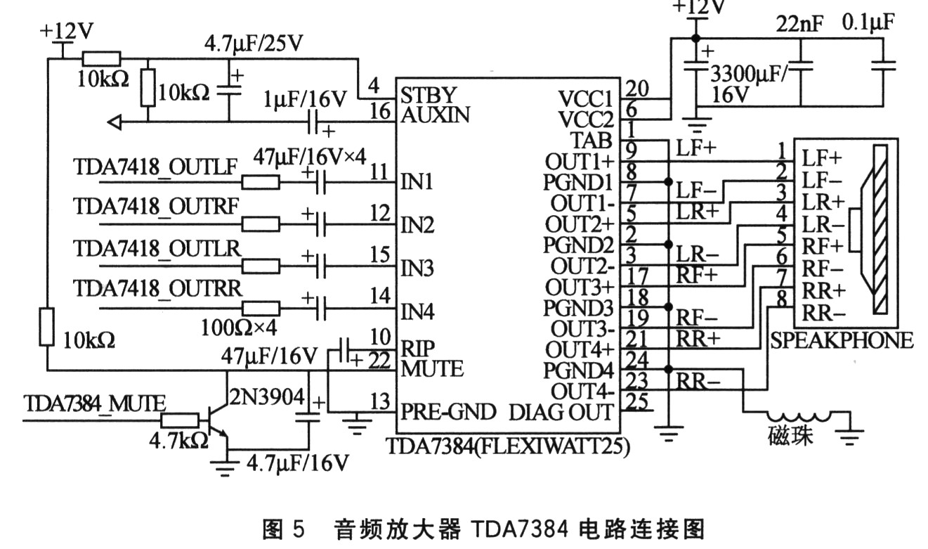
The external communication interface of the radio module Si4730 is the I2C bus, which is hung on the system I2C bus. The AML8613 can set its related registers. The audio signal from the radio and the AML8613 is very weak and there is not enough power to drive the car stereo. They are input to the audio amplifier TDA7384 via the audio multiplexer. The specific circuit connection is shown in Figure 5.
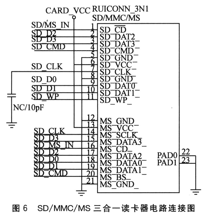
(. 4) and the USB HOST interface unit SD SD interface read SD / MMC / MS data, AML8613 integrated SD interface, one card reader may be connected directly to the pins corresponding AML8613 chip. SD_CMD, SD_CLK, SD_WP, SD/MS_IN, SD-DO to SD_D3 need to be connected to a 4.7 kΩ pull-up resistor. The specific circuit is shown in Figure 6.
(5) Touch screen interface unit The system uses a four-wire resistive touch screen, which requires a dedicated touch screen A/D sampling chip TSC2003I, and the touch screen pins are respectively connected to the chip pins X+/X-/Y+/Y-. When there is a click on the touch screen, TSC2003I will notify the master chip AML8613 through the I2C bus in real time. Its circuit connection is shown in Figure 7.
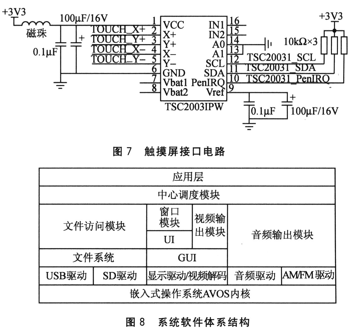
4 software design car audio and video entertainment system is a real-time embedded systems. The system software architecture consists of four parts from the bottom up, namely embedded real-time operating system layer, driver layer, function module layer and application program, as shown in Figure 8. At the bottom is the embedded operating system layer, here is the AVOS operating system developed by Amlogic itself. The file system supports formats such as FAT/FAT32/NTFS. File Access module functions include: to enter the directory INT32S FileNavCD (CHARSTR * pCD-Path), reading the current directory CHARSTR * FileNa-vGetCurrDir (void), refresh the current directory INT32S FileNa-vRefreshCuurem Dir (void), read the next file List INT32S FileNavGetNextFileList(PAX, HNODE*pDesList, INT32U*pListLength, INT32U iGet-ListFlag), read the previous page file list, search the file list, read the current file directory, read the current file list display file type, file list Scroll up and down, enter the file directory, read the current directory name, enter the device directory, and so on.
Video decoding includes RM, RMVB, AVI, MPEG1/2/4, DIVX, XVID, VOB, AVI, DAT, M-JPEG, JPG, BMP, TIFF, PNG, GIF. The system uses an embedded GUI (Graphic User Interface). An embedded GUI system is a graphical user interface system designed for a specific hardware device or environment in an embedded system.
Audio drivers include MP3, WMA, and AAC decoding. The audio output module functions comprising: initializing the playlist INT32S AWPlayListInit (INT32S list_num, INT32U * list_media_type, INT16U * max_list_item_num), add the playlist item INT32SAWAddPlaylistItem (char * item_path, INT3 2 S item_media_t, INT16U item_index), the reading of the playlist A file char*AWGetFirstlistIterm(INT32U media_type), set the play mode, clear the playlist, create a playlist, and so on.
The system establishes a central scheduling module, which is responsible for interacting information between the application layer and other functional modules (such as file access module, window module, video output module, audio output module, etc.), and scheduling each module application according to peripheral requirements. While maintaining the state of each functional module. The system waits for a user event to occur while the system is working. Once the user event is received, the system will call the corresponding function module to complete the user-specified function. When the end signal is received or the program ends, an end signal is sent to the central scheduling module, and the occupied resources are released.
The application layer is the highest layer of the software framework, and the user application code is written, which mainly completes the coordinated operation between the modules of the car entertainment audio and video system.
5 Conclusions In view of the high price and difficult popularity of DVD car audio and video systems, a new generation of car audio and video system solutions is proposed, replacing the high-cost audio and video system with DVD movement as the carrier, providing audio and video source through storage media and supporting multiple videos. , audio format, is a low-cost car multimedia system. Both the hardware and software systems have been tested and run well, enabling smooth playback of video streams and radio AM/FM in multiple formats. It takes into account the car playback function and versatility, and also makes up for the shortcomings of the traditional car audio and video system, and has a good market application prospects.
Vetch Honey,Pure Milk Vetch Honey,Nature Milk Vetch Honey,Ripe Vetch Honey
Bee Products Co., Ltd. , http://www.nsbeeproducts.com