Some time ago, a slightly special power supply, during the debugging process, found the bridge pile is very strange heat.
Share the problem finding and resolution process here.
Before the bottom of the game was revealed, I hope that netizens will actively analyze the reasons.
Let me talk about it first. This power supply requires two independent PFCs due to special requirements.
The two sets of independent PFCs output power to the two sets of subsequent circuits, and two sets of isolated electronic loads are used during the debugging process. As shown below:
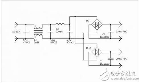
The two roads are fully loaded and everything is normal.
Added a cartoon picture, which looks like a bit.
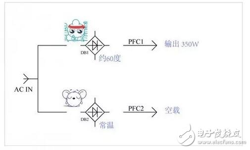
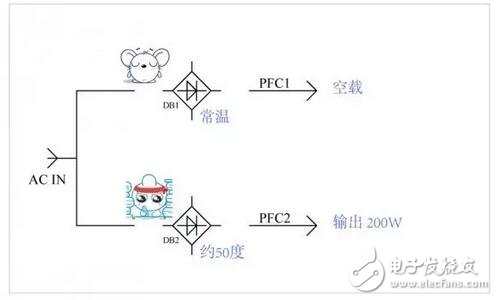
In front, everything went well.
Both roads can be loaded normally, well, this time together with the load.
The problem can be solved: when the two roads are loaded together, the bridge pile of the second road is obviously much warmer than when it is loaded alone.
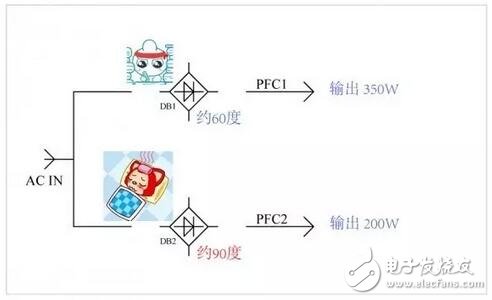
After repeated testing, the phenomenon is:
As long as one road has a large load, the 2-way bridge stack will heat up, and the one-way bridge will be reduced to a small or no-load, and the 2-way bridge stack will immediately cool down.
Is this really a haunt?
With a large load of 350W, instead of carrying 200W of bridge heat.
And I also carried it myself, making it hot next door.
This is called: playing cattle across the mountain?
first reaction:
Is the principle drawing wrong, resulting in the PCB is also wrong, the two sides of the bridge piled current?
After inspection, there is nothing wrong, it has indeed been separated, not a stream.
It is suspected that the CBB capacitance of each PFC is not large enough, and the two channels simultaneously double the capacity.
As a result, the second road bridge pile was obviously cooled, but whether it dropped to the normal value, there was not too much attention.
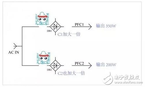
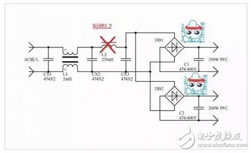
Also tried, C1, C2 restore, short circuit L2, the same result.
The second road bridge pile also cooled significantly.
Also tried, C1, C2 restore, L2 also restore, only increase CX3, the same result.
The second road bridge pile also cooled significantly.
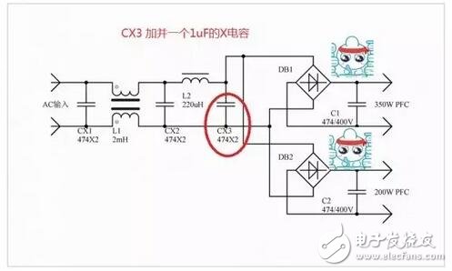
Trying so many ways, that is, increasing the capacitance can significantly reduce the temperature of DB2.
It is estimated that many engineers have come to this and feel that the problem has been solved.
Don't care about why it was hot before, add a capacitor and why it is not hot.
This may be a tight project, time is not allowed, and it will be fine.
Or you can use it yourself, there is no need to know why.
In fact, as a research and development technician, you should try to find the reason within your ability.
This is a responsible attitude towards yourself, the product, and the company.
The attitude of doing things is very important.
Looking back, what are the common reasons for bridge stacks (or diodes) to heat up?
The most common: the current is large (the two outputs are not connected, this is also confirmed before the suspect)
Reverse short-term soft breakdown (do not rule out this possibility)
Later, I think about it, it can't be a reverse recovery problem.
Thinking of this, suddenly a bright light, I feel that this possibility is very large, ready to verify.
Correction method: Replace the heated rectifier bridge with a quick recovery tube.
Replace the two diodes of the positive pole of DB2 with an ultrafast recovery diode.
The temperature is also significantly reduced.
Look at the input power, which is about 1W lower than the input power of the previous capacitor.
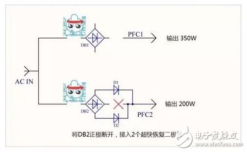
In fact, the current waveform was measured with a current probe and a bridge current and a fast tube.
When using the "slow tube", the reverse current can be measured, and it is quite large.
The reason is that it has been determined that the bridge reactor reverse recovery is slow and causes heat. The figure below illustrates the specific reasons, and it also explains why doing the above changes can reduce the fever of DB2.
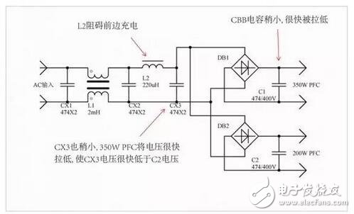
At this point, the ghost has been found, and then look at what is the appropriate way to destroy it. The use of the fast tube is of course the most direct way, the right medicine.
But this way, I feel more troublesome, and maybe even people who are caught by the industry laugh at me: 50Hz with a fast tube.
The final solution is to remove the differential mode inductance in front of the bridge and add differential mode inductance to the two channels.
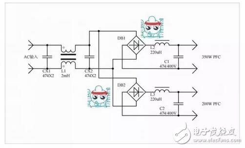
summary
One-way PFC quickly pulls down its own CBB capacitor and the CBB capacitor voltage on the front of the bridge.
The voltage of the other bridge stack is quickly reversed (the front side is lower than the back side), and if the bridge pile is charging the back side, the current will be reversed due to the slow reverse recovery.
In fact, another bridge push may also have this problem, just because the power on both sides is different, so that the power side can pull the front voltage lower (or pull lower), so the bridge with low power. The heat of the pile is more obvious.
To achieve this problem, several conditions must be met:
1. The CBB capacitance of at least one side of the bridge stack is too small, causing the voltage to be pulled down quickly.
2. The CBB capacitance in front of the bridge stack is also small, and at the same time it is pulled down quickly.
3. The input string has a differential mode inductance (if the common mode leakage inductance is large enough, it is also OK), hindering the fast charging at the back.
4. The bridge stack is a slow tube with a large reverse recovery current.
The above four conditions, the first three conditions are the cause of the current has a chance to reverse flow.
The reason for the fever is that the reverse recovery speed of the bridge stack is too slow.
China Home Ev Charger,Wall-Mounted Ac Ev Charging Station manufacturer, choose the high quality Wall-Mounted Ac Ev Charger,Wall-Mounted Ac Ev Charging Pile, etc.
Home Ev Charger,Wall-Mounted Ac Ev Charging Station,Wall-Mounted Ac Ev Charger,Wall-Mounted Ac Ev Charging Pile
Shenzhen Hongjiali New Energy Co., Ltd. , https://www.hjlcharger.com