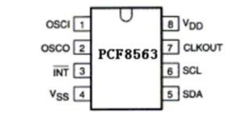
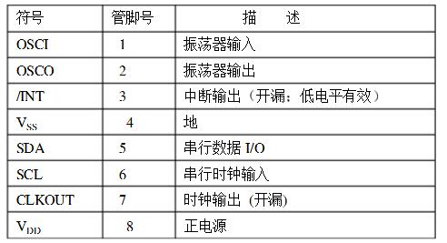
The PCF8563 is an industrial-grade multi-function clock/calendar chip with very low power consumption that includes an I2C bus interface function from PHILIPS. The PCF8563's various alarm functions, timer functions, clock output functions, and interrupt output functions can perform a variety of complex timing services, and even provide a watchdog function for the microcontroller. It is a very cost-effective clock chip, which has been widely used in electric meters, water meters, gas meters, telephones, fax machines, portable instruments and battery-powered instruments.
Pcf8563 featuresThe low operating current is typically 0.25AVDD=3.0VTamb=25;
Century mark
Large working voltage range of 1.0-5.5V;
The low sleep current is typically 0.25A (VDD = 3.0V, Tamb = 25);
400KHz I2C, bus interface VDD = 1.85.5V;
The programmable clock output frequency is 32.768KHz1024Hz32Hz1Hz;
Alarm and timer;
Internal integrated oscillator capacitor, on-chip power reset function, brownout detector;
The I2C bus reads 0A3H from the address and writes 0A2H;
Open drain interrupt pin
Pff8563 block diagram
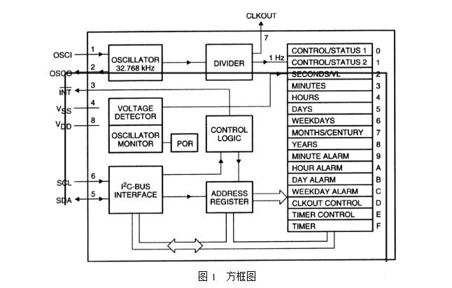
The PCF8563 has 16 8-bit registers: an auto-incrementable address register, a built-in 32.768KHz oscillator (with an internally integrated capacitor) and a divider (used to provide the source clock to the real-time clock RTC). Program clock output, a timer, an alarm, a brownout detector and a 400KHz I2C bus interface.
All 16 registers are designed as addressable 8-bit parallel registers, but not all bits are useful. The first two registers (memory addresses 00H, 01H) are used for control registers and status registers, memory addresses 02H~08H are used for clock counters (seconds to years counters), addresses 09H~0CH are used for alarm registers (definition alarm conditions), addresses 0DH controls the output frequency of the CLKOUT pin. Addresses 0EH and 0FH are used in the timer control register and timer register, respectively. Second, minute, hour, day, month, year, minute alarm, hour alarm, day alarm register, encoding format is BCD, week and week alarm registers are not encoded in BCD format. When an RTC register is read, the contents of all counters are latched, so misreading of the clock calendar chip can be disabled under transfer conditions.


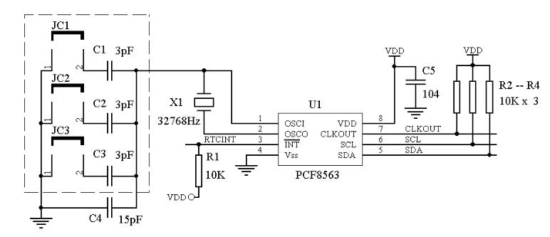
Figure 1 PCF8563 high precision adjustment
Related instructions:As shown in Figure 1, R3 and R4 are I2C bus pull-up resistors. If the bus speed is higher than 100KHz, the resistance value is smaller. Since the interrupt output and clock output of the PCF8563 are open-drain outputs, an external pull-up resistor (such as R1 and R2 in Figure 1) is required. If these two signals are not used, the corresponding pull-up resistors may not be used. For the PCF8563 chip, an external clock crystal oscillator of 32768 Hz (see X1 in Figure 1) is required. It is recommended to use a crystal of 5 ppm or more. The PCF8563 typical application circuit recommends a 15pF crystal matching capacitor, which can be adjusted in practical applications to enable the RTC to obtain a higher precision clock source. Generally, the crystal matching capacitor is adjusted between 15pF and 21pF (relative to the 5768MHz crystal oscillator with 5ppm accuracy). The clock frequency is slightly higher when the 15pF capacitor is used, and the clock frequency is slightly lower when the 21pF capacitor is used.
Operation method:1. Set PCF8563 clock output valid (CLKOUT), the output frequency is 32.768KHz.
2. Use a high precision frequency meter to measure the frequency of the CLKOUT output.
3. Short-circuit or disconnect the JC1, JC2, and JC3 according to the measured frequency. When the frequency is higher than 32768Hz, increase the capacitance value; when the frequency is lower than 32768Hz, reduce the capacitance value.
Note: The values ​​of C1, C2, and C3 in Figure 1 are between 1pF and 5pF, and the combination is determined according to the actual situation, so as to facilitate rapid adjustment. It is recommended to use (3pF, 3pF, 3pF), (1pF, 2pF, 3pF), (2pF, 3pF, 4pF).
Android is an open source mobile operating system based on Linux platform released by Google at the end of 2007, and then improved for use in netbooks and MIDs. The platform consists of operating system, user interface and application software, and is claimed to be the first truly open and complete mobile software for mobile terminals.
To put it simply, the Android system is actually a very open system. It can not only realize the functions of the most commonly used notebook computers, but also realize various directional operations like mobile phones. Moreover, it is specially designed for mobile phones. The operating system developed for equipment has advantages in system resource consumption and human-computer interaction design. It is an operating system that combines traditional and advanced advantages.
New Android Tablet,Android Tablet,New Android Tablet
Jingjiang Gisen Technology Co.,Ltd , https://www.jsgisengroup.com