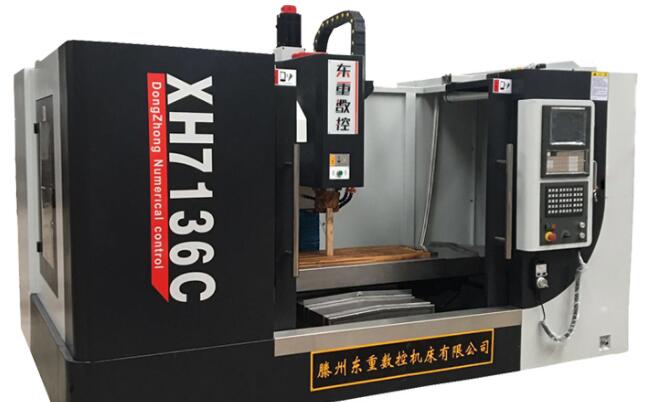
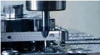
The spindle drive system is the part of the power plant that completes the main motion in the system. It drives the workpiece or tool to make corresponding rotational movements so that it can match the feed motion and process the ideal parts. There are two main forms of mainshaft drive gear shifting at present: First, gear shifting of the spindle motor aims to reduce the spindle speed, increase the gear ratio, and amplify the spindle power to meet the need of cutting; second, the spindle motor is driven by synchronous toothed belt or belt. Spindle, this type of spindle motor, also known as wide-range motor or strong cutting motor, with constant power characteristics. Because there is no need for mechanical transmission, the gears and clutches are saved in the headstock, and the headstock actually becomes a spindle support, which simplifies the main drive system and improves the reliability of the transmission chain.
I. Requirements of CNC machine tools for spindle drive systemsThe spindle drive system is the power device that completes the main motion in the CNC system. The spindle drive system converts the cutting torque and cutting speed of the tools installed on the spindle (such as the CNC milling machine and machining center) or the workpiece (such as the CNC lathe) through the transmission mechanism, and processes the ideal parts with the feed motion.
1. Wide speed range and stepless speed regulation
2, a wide range of constant power
3, with 4 quadrant drive capability
4, with position control capabilities
5, with high accuracy and stiffness, smooth transmission, low noise
6, good vibration resistance and thermal stability

1. FANUC Spindle Drive System
Since the 1980s, FANUC has used the AC spindle drive system. The DC drive system has been replaced by the AC drive system. At present, the three series of AC spindle motors are: S series motors, rated output power range 1.5~37kW; H series motors, rated output power range 1.5~22kW; P series motors, rated output power range 3.7~37kW. The characteristics of the company's AC spindle drive system are:
1) Use microprocessor control technology to perform vector calculation to achieve optimal control; 2) The main loop uses a transistor PWM inverter to make the motor current very close to a sinusoidal waveform;
3) With spindle orientation control, digital and analog input interfaces and other functions.
2. SIEMENS spindle drive system
The DC spindle motor produced by SIEMENS Company has four series of 1GG5, 1GF5, 1GL5 and 1GH5. The 6RA24 and 6RA27 series drive devices matched with the above four series motors adopt thyristor control.
In the early 1980s, the company introduced two series AC spindle motors, 1PH5 and 1PH6, with a power range of 3 to 100kW. The drive is
6SC650 series AC spindle drive or 6SC611A (SIMODRIVE611A) spindle drive module, the main circuit using transistor SPWM frequency conversion control, with energy regeneration braking function. In addition, the microprocessor 80186 can perform closed-loop speed, torque control and magnetic field calculations to complete the vector control.

1, external interference
Due to electromagnetic interference, poor shielding and grounding measures, the spindle speed command signal or feedback signal is disturbed, causing spindle drive to randomly and irregularly fluctuate. The method of distinguishing whether there is interference or not is: when the spindle speed command is zero, the spindle will still reciprocate, and adjusting the zero speed balance and drift compensation will not eliminate the fault.
2, overload
Excessive cutting amount, frequent positive, reverse, etc. can cause overload alarm. The specific performance of the spindle motor overheating, spindle drive system display over-current alarm.
3, spindle positioning jitter
Spindle accurate stop for tool exchange, fine retraction and gear shifting, etc., there are three ways to achieve:
(1) Mechanical quasi-stop control
(2) Electrical quasi-stop control of magnetic sensor
(3) Encoder-type accurate stop control
4, spindle speed and feed does not match
When performing thread cutting or cutting with the feed command per revolution, there will be a failure to stop feeding and the spindle will continue to run. To execute a command for feed per revolution, the spindle must have a feedback signal for each revolution of the spindle. Normally, there is a problem with the spindle encoder. It can be determined in the following ways:
1) Alarm display on the CRT screen.
2) Call the machine data or I/O status via the CRT to observe the signal status of the encoder.
3) Use the feed instruction per minute instead of feed per revolution to execute the program and observe if the fault disappears.

5, speed deviation from the command value
When the spindle speed exceeds the range specified by the technical requirements, consider:
1) The motor is overloaded.
2) The analog value of the spindle speed output by the CNC (usually 0 to +10V) does not reach the value corresponding to the speed command.
3) The speed measuring device is faulty or the speed feedback signal is disconnected.
4) Failure of the spindle drive.
6. Spindle abnormal noise and vibration
First, it is necessary to distinguish whether abnormal noise and vibration occur in the mechanical part of the spindle or the electric drive part.
1) In the deceleration process, it is generally caused by another driving device, such as the failure of the regeneration circuit in the AC drive.
2) Generated at a constant speed, can be distinguished by observing whether there is noise and vibration in the process of the free stop of the spindle motor. If it exists, the mechanical part of the spindle has a problem. 3. Check whether the vibration period is related to the rotation speed. If irrelevant, the spindle drive is generally not adjusted properly; if relevant, check whether the mechanical part of the spindle is good and whether the speed measuring device is defective.
7, spindle motor does not turn
From the CNC system to the spindle drive, in addition to the speed analog control signal, there is an enable control signal, which is typically a DC+24V relay coil voltage.
1) Check whether the CNC system has a speed control signal output.
2) Check to see if the signal is on. Observe the status of I/O by CRT and analyze the machine PLC graphic (or flow chart) to determine whether the spindle start conditions, such as lubrication, cooling, etc. are satisfied.
3) Failure of the spindle drive.
4) Spindle motor failure.

Fault phenomenon
When the 1.8m sleeper spindle stopped, it made a loud noise, but the insurance did not burn out.
an examination
Use the diagnostic board to readjust the system parameters according to the instructions in the manual. During the adjustment process, the line time should be 15s, but it has been adjusted to 10s during the fault. In addition, the position of the gain potentiometer is adjusted higher than required. Even if the gain increases.
analysis
The so-called line time refers to the rise and fall time of the system. For the control system of the motor controlling the 56 kW motor, the line time was changed from 15 s to 10 s, then the mechanical inertia generated by the motor would make a huge noise on the gear when the vehicle was stopped, thus causing the gear to be damaged.
Increasing the gain can reduce the dead zone and reduce the speed error. However, if the gain is too large, the overshoot will be serious, which will cause trouble for the transient response of the system. In addition, the decrease of the line time will increase the mechanical noise.
The various parameters in the drive system must be strictly calculated and determined on the basis of the actual conditions of each motor and machine. Although the machine tool has been running for many years, some of the parameters have also changed, but this change It is extremely small. Under normal circumstances, the position of each potentiometer arrow should not be arbitrarily changed.
deal with
(1) Adjust the line time to 15s (2) to decrease the gain.
We are dedicated charging solution Manufacturer since 2005.
Supply various Power Station including Portable Power Stations, Solar Power Generators, Smallest Generator etc.
Manufacturing high quality products for customers according to international standards, such as CE ROHS FCC REACH UL SGS BQB etc.
To constantly offer clients more innovative products and better services is our consistent pursuit.
portable power stations for camping, solar pow er stations, jackery portable power station
TOPNOTCH INTERNATIONAL GROUP LIMITED , https://www.micbluetooth.com