Switching regulated power supplies consist of multiple electronic devices, but in essence, the core of a switched-mode power supply is a DC transformer. Therefore, it is not difficult to analyze the switching regulated power supply. In this article, Xiao Bian will introduce the control options and efficiency improvement options for program-controlled switching power supplies.
Control method selectionSolution one: Use the one-chip computer to produce PWM wave, control the switch on and cut off. The duty cycle is changed according to the on-chip AD feedback sampling voltage to stabilize the output voltage at the set value. The load current is sampled on the copper wire and input to the SCM after on-chip AD. When the voltage reaches a certain value, the switch tube is turned off to form an over-current protection. The program is mainly implemented by software. The control algorithm is more complex, slower, and the output voltage stability is not good. If you want to achieve automatic recovery, it is more complicated to implement.
Solution 2: Use the constant frequency pulse width modulation controller TL494. This chip can be push-pull or single-ended output. The operating frequency is 1kHz~300kHz, the output voltage can reach 40V, there is a 5V voltage reference, the dead time can be adjusted, and the output The level of pull irrigation current up to 200mA, driving ability. There are two error comparators inside the chip, a voltage comparator and a current comparator. The current comparator can be used for over-current protection and the voltage comparator can be set for closed-loop control with quick adjustment.
Therefore, through the above analysis, it is recommended to use the second option.
Current mode selectionOption one: continuous current mode
When the current is continuous, the current in the inductor has not been reduced to zero when the next cycle comes. The current of the capacitor can be supplemented in time, the peak value of the output current is small, and the output ripple voltage is small.
Option Two: Current Interruption Mode
In the discontinuous mode, when the inductor energy is released, the next cycle has not yet arrived, the capacitor energy is not replenished in time, the peak current of the diode is very large, the requirements for the switch tube and the diode are very high, and the loss of the diode is also very large. Moreover, since the current is intermittent, the AC component of the output current is relatively large, which increases the loss on the output capacitor. For the same power output, the peak current in the intermittent operation mode is much higher, and the ripple of the output DC voltage also increases and the loss is large.
In light of the above analysis, this design uses Option One.
Increased efficiency optionsFactors that affect efficiency include the power consumption of the microcontroller and peripheral circuits, the efficiency of the microcontroller and peripheral circuit power supply circuits, and the efficiency of the DC-DC converter. The design uses an ultra-low-power microcontroller MSP430F169, high conversion efficiency of the chip to power the peripheral circuits, and the use of low-loss components and excellent control strategy.
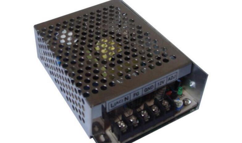
"Switching regulated power supply" is more efficient and energy-saving than "series-regulated regulated power supply"; it is adaptable to changes in commercial power; the output voltage can be adjusted in a wide range; a switch can easily obtain multiple sets of different voltage levels. Power supply; small size, light weight and many other advantages, and is widely used.
(1) Low power consumption and high efficiency
(2) Small size and light weight
(3) Wide voltage range
(4) The efficiency of filtering is greatly improved, which greatly reduces the capacity and volume of the filter capacitor.
(5) Flexible and diverse circuit types
Disadvantages:The disadvantage of switching regulated power supplies is that there are more serious switching disturbances. In a switching regulated power supply, the power-adjusting switching transistor operates in a state where the AC voltage and current it generates cause spike interference and galvanic interference through other components in the circuit. If these disturbances are not taken, certain measures are taken to suppress, eliminate, and shield the interference. , it will seriously affect the normal work of the machine. In addition, because the switched-mode power supply oscillator has no isolation of the power frequency transformer, these disturbances will be connected to the power frequency grid, causing serious interference to other nearby electronic instruments, equipment and household appliances.
Four switching power supply circuit circuits: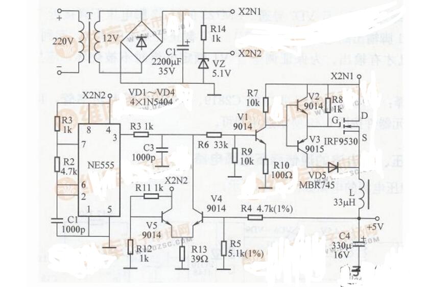
Circuit works: 220V voltage transformer T step down, VD1 ~ VD4 rectification, C1 filtering, as input. In addition, VD5, VD6, C2, and C3 form a voltage doubler circuit (makes Vd=60V); RP and R3 form a voltage divider circuit; TL431 and R1 form a sampling amplifier circuit; 9013 and R2 form a current limit protection circuit, and the MOSFET K790 adjusts Tube (can be used directly in parallel); C5 is the output filter capacitor. The voltage regulation process is: When the output voltage decreases, the voltage at the point f decreases, and the internal voltage of the TL431 amplifies the voltage at the point e. After adjustment by the K790, the voltage at the point b rises. Conversely, when the output voltage increases, the voltage at the point f rises. The potential at point e decreases, and the potential at point b decreases after adjustment by K790, thereby stabilizing the voltage at the input. When the output current is greater than 6A, the transistor 9013 is turned off, so that the output current is limited to 6A, so as to achieve the purpose of current limiting.
Component selection: The circuit uses 2W for the resistor RI and 5W for the R2. There are no special requirements for other components. Select them as shown in the figure.
Circuit two: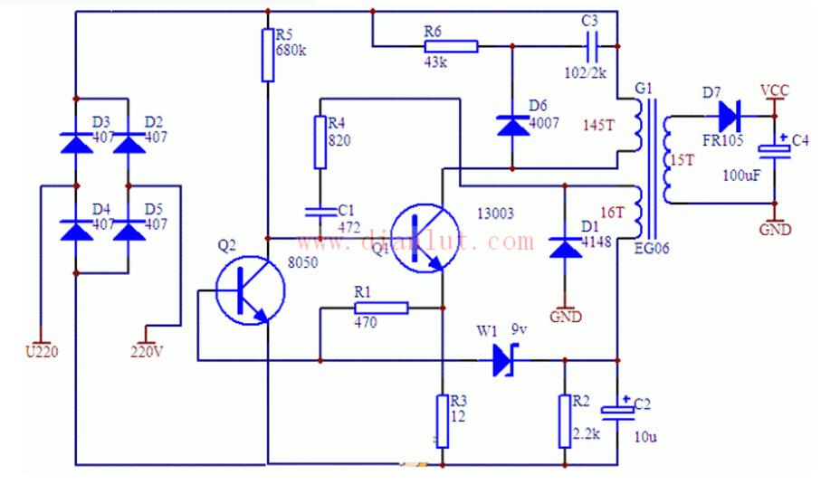
The 115V AC input voltage is rectified and filtered to provide the DC operating voltage for the circuit. The starting circuit is composed of capacitor C2 and resistor R2. C2 is charged by resistor R2. When it reaches 16 V, UC3842 has an output; MOS switch Q1 is turned on and energy is stored in transformer T1. At this time, due to the secondary side The rectifying diode is reverse-biased, so the energy cannot be transmitted to the secondary side of T1. The primary current on T1 side is detected through the resistor R10 and compared with the 1 V reference voltage provided inside the UC3842. When this level is reached, Q1 turns off. . The winding polarity of all transformers is reversed, and the output rectifier diodes are forward biased, and the energy stored in T1 is transferred to the output capacitor. After the start-up is completed, the voltage of the feedback coil is rectified and then divided by the sampling resistor and returned to the reverse side of the error amplifier (pin 2) to compare with the 2.5 V reference voltage inside the UC3842 to adjust the drive pulse width. This changes the output voltage to control the output. This energy is stored and released periodically, supplying voltage to the various outputs.
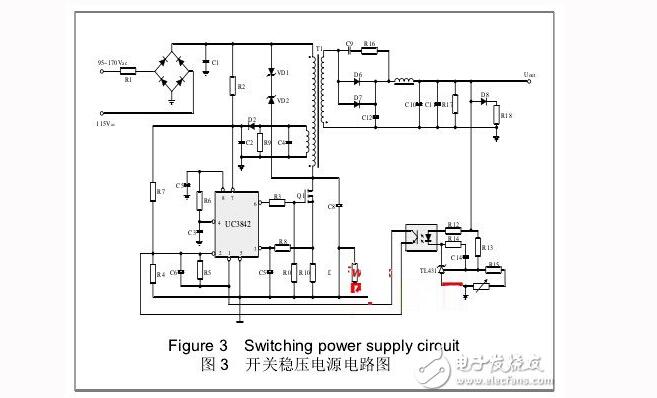
Regulator feedback environment consists of R12, optocoupler, TL431 and other components. The voltage regulation principle: if the output voltage rises due to a lighter load, the LED current flowing through the optocoupler increases, the luminous intensity increases, and the feedback to the optocoupler triode causes the resistance between the CEs to decrease, adding to 1 The voltage of the foot is lowered, thereby narrowing the width of the PWM signal of the 6-pin to achieve the purpose of voltage regulation.
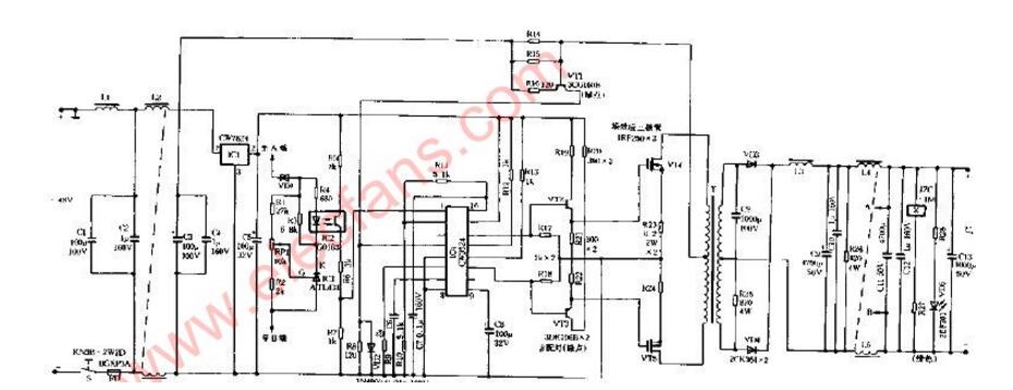
Circuit four:24V (-40V) Switching Regulator Power Supply Circuit Diagram
Ningbo Autrends International Trade Co.,Ltd. , https://www.vapee-cigarettes.com