The CAN bus terminating resistor, as the name implies, is the resistor applied to the end of the bus. Although this resistor is small, it plays an important role in CAN bus communication.
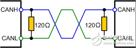
There are two functions of the CAN bus terminating resistor:
First, improve the anti-interference ability, ensure that the bus quickly enters the hidden state.
Second, improve signal quality.
Improve anti-interference abilityThe CAN bus has two states: "dominant" and "recessive". "dominant" stands for "0" and "recessive" stands for "1", which is determined by the CAN transceiver. Figure 1 is a typical internal structure diagram of a CAN transceiver, CANH, CANL connection bus.
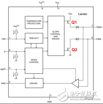
figure 1
When the bus is dominant, the internal Q1 and Q2 of the transceiver are turned on, and the voltage difference is generated between CANH and CANL. When recessive, Q1 and Q2 are cut off, CANH and CANL are in a passive state, and the voltage difference is 0.
If there is no load on the bus, the differential resistance of the differential is very large, and the external interference requires only a small amount of energy to make the bus dominant (the general transceiver dominant threshold minimum voltage is only 500mV). In order to improve the anti-interference ability of the bus recessive, a differential load resistor can be added, and the resistance value is as small as possible to eliminate the influence of most noise energy. However, in order to avoid the need for an excessive current bus to enter the dominant, the resistance should not be too small.
Ensure fast entry into recessive stateDuring the dominant state, the parasitic capacitance of the bus is charged, and when it returns to the recessive state, these capacitors need to be discharged. If no resistive load is placed between CANH and CANL, the capacitor can only be discharged through the differential resistor inside the transceiver. We add a 220PF capacitor between the CANH and CANL of the transceiver for simulation test. The bit rate is 500kbit/s, and the waveform is shown in Figure 2 and Figure 3.
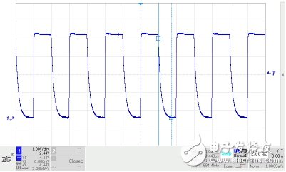
figure 2
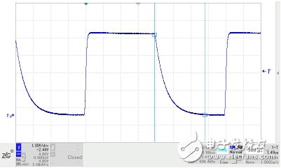
image 3
It can be seen from Fig. 3 that the explicit recovery to recessive time is as long as 1.44 μS, and it is barely able to communicate when the sampling point is high. If the communication rate is higher, or the parasitic capacitance is larger, it is difficult to ensure normal communication.
In order to quickly discharge the bus parasitic capacitance and ensure that the bus enters the recessive state quickly, a load resistor needs to be placed between CANH and CANL. After adding a 60Ω resistor, the waveform is shown in Figure 4 and Figure 5. It can be seen from the figure that the time for explicit recovery to recessiveness is reduced to 128 nS, which is equivalent to the dominant setup time.
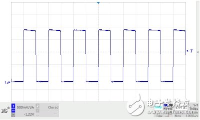
Figure 4
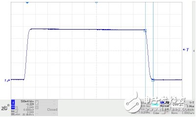
Figure 5
Improve signal qualityWhen the signal edge energy encounters an impedance mismatch at a higher slew rate, signal reflection occurs; the geometry of the transmission cable cross-section changes, the characteristic impedance of the cable changes, and the reflection .
At the end of the bus cable, the sharp change in impedance causes the edge energy of the signal to reflect, and ringing occurs on the bus signal. If the ringing amplitude is too large, the communication quality will be affected. Add a terminating resistor that matches the characteristic impedance of the cable at the end of the cable to absorb this energy and avoid ringing.
We conducted a simulation test with a bit rate of 1 Mbit/s. The transceivers CANH and CANL were connected to a twisted pair of about 10 m. The transceiver was terminated with a 120 Ω resistor to ensure the implicit conversion time, and the end was not loaded. The end signal waveform is shown in Figure 6. The ringing of the signal rises.
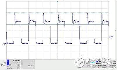
Figure 6
If a 120Ω resistor is added to the end of the twisted pair, the end signal waveform is significantly improved and the ringing disappears, as shown in Figure 7.
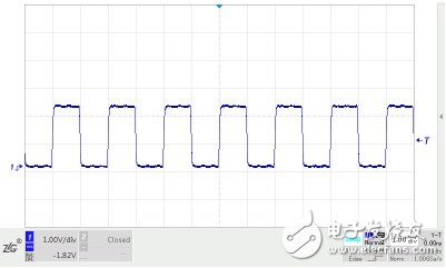
Figure 7
Generally, in a linear topology, both ends of the cable are the transmitting end and the receiving end, so each end of the cable needs to be added with a terminating resistor.
Why choose 120Ω?The characteristic impedance of any cable can be obtained experimentally. One end of the cable is connected to the square wave generator, and the other end is connected to an adjustable resistor, and the waveform on the resistor is observed through an oscilloscope. Adjust the resistance value until the signal on the resistor is a good square wave without ringing. The resistance value at this time can be considered to be consistent with the characteristic impedance of the cable.
Most car cables are single-wire. If you use a typical cable used in two cars and twist them into twisted pairs, you can get a characteristic impedance of about 120Ω according to the above method, which is also the recommended terminal resistance of the CAN standard.
This series is an effect maker on the stage, including laser lights with multi-segment shape changes, electrodeless lights with sudden changes in color angles, matrix lights that can display fixed patterns or letters, etc., both in color and light shape. outstanding effect. The laser light has been edited to show a 3D stereoscopic effect. With the delay effect in the venue, the laser light with strong penetrating power can show a more beautiful effect. If you want the stage to be more cool, the effect light series is also an essential option.

Stage Effect And Laser Lights,Laser Light,Disco Laser Light,Sky Laser Light
Guangzhou Cheng Wen Photoelectric Technology Co., Ltd. , https://www.cwdisplay.com