Cranes are a common handling tool in factories and workshops. Its power is generally an AC motor. The crane can run up, down, left, right, front and back in space. There are two general methods for controlling the crane: one is that the operator controls the operation room suspended on the crane beam; the other is that the button for controlling the motor is led to the ground by the control line, and the operator controls the ground. However, in the work, I feel that these two methods are not convenient, so I designed the infrared remote control to control the crane system.
First, the working principleThe system consists of an infrared transmitter (referred to as a transmitter) and an infrared receiver (referred to as a receiver). There are 8031 ​​microcontrollers in both the transmitter and receiver, with a full-duplex serial interface. The communication between the two machines is based on the serial port.
The two 8031 ​​single-chip microcomputers of this remote control device transmit information by infrared light. The output end of the transmitter serial port drives the infrared light emitting diode to transmit the digital information into an infrared light pulse signal. The infrared detection amplifier restores the infrared light signal to a digital signal, and sends it to the receiving serial input terminal. After 8031 ​​recognition processing, the corresponding control is made.
The serial interface of the 8031 ​​MCU has four working modes. This system adopts mode 1, which is an 8-bit asynchronous communication method with variable baud rate. Considering the switching time of the infrared light-emitting diode and the infrared detector, we set the transmission baud rate to 1 250 b/s.
The serial port of the transmitter 8031 ​​is defined as the mode 1 output, and the command input by the keyboard is converted into a frame of information, and the on and off of the infrared light pipe are controlled to transmit the information.
The serial port of the receiver 8031 ​​is defined as a mode 1 input, and receives digital information converted by the infrared detector.
Second, the system hardware circuit and program design1. Transmitter hardware circuit and program design
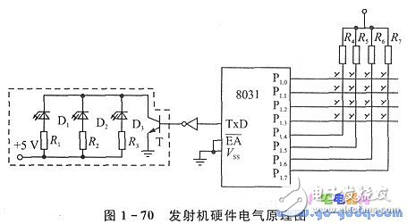
The schematic diagram of the infrared remote transmitter is shown in Figure 1-70.

The 8031 ​​minimum system is composed of 8031, 74LS373 and 2732 EPROM, crystal oscillator, reset circuit, and the like. 4&TImes; 4 keyboard is connected to P31 port of 8031, P1.o~Pl.3 is set as output, P1.4~P1.7 is set as input, and the keyboard is scanned by query mode.
The dotted line is the infrared light emitting circuit. D1 and D2 are infrared light emitting diodes; D3 is an infrared light emitting diode as an indicator. They are all driven by a triode T. The serial port output (TxD) controls the conduction and deactivation of the transistor T via the inverter. When TxD =0, T is turned on, D1, D2, and I]3 are illuminated; when TxD is =1, T is turned off, and no current flows through D1, D2, and D3, and no light is emitted.
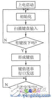
The block diagram of the infrared remote transmitter is shown in Figure 1-71.

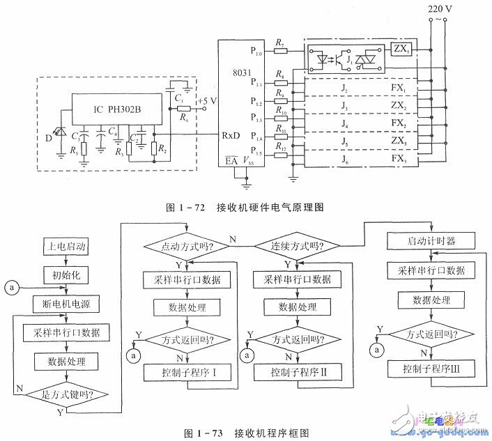
In addition to the 8031 ​​microcontroller part, the receiver also has an infrared signal receiving portion and a control output portion. Figure 1-72 is the electrical schematic of the receiver.
The dotted box is a partial circuit diagram of the infrared receiver. D is an infrared detector diode and IC PH302B is an infrared amplifier. The infrared light signal is detected and amplified and sent to the input end (RxD) of the serial port of the 8031 ​​microcontroller. When there is enough infrared light to illuminate D, the 7th end of the IC changes from 1 to 0.
The P1 port of the receiver 8031 ​​serves as an output control interface. P1.0 to P1.6 control six solid relays J1 to J6. Solid state relays are a new type of relay suitable for microcomputer control. The inside has a photocoupler and a bidirectional thyristor, which blocks the electrical connection between the microcomputer system and the main circuit, and does not generate an electric spark when passing or breaking, thereby causing adverse effects to the microcomputer. The output of J1-J6 can be used directly as a control switch for the contactor coil. J1j2, J3J4 and Js Figure 1-71 Transmitter program flow chart J6 controls the positive and negative rotation of three motors, and the positive and negative blocking of each motor and three
Interlocking between motors is done by software. This not only saves a lot of relays, reduces the size of the control panel, but also removes the hidden troubles. The block diagram of the receiver is shown in Figure 1-73.

The infrared remote transmitter can control the crane operation in three ways:
â— Jog mode This is the control method of the original system, that is, press the button to start the motor until it is released;
â— Press the key once in continuous mode to execute the operation of the key, and press it again to stop the operation;
â—Teaching mode The operator "teach" the crane running process to the crane by jog or continuous motion. The crane will put the crane
The process is written down and then it can be repeated automatically. This method is especially suitable for repetitive handling.
The control distance of the remote control device is greater than 80 m, and the control angle is not less than 120. (It can also be designed in all directions), it is suitable for short-distance remote control. The control distance can be increased by increasing the transmission power of the infrared light pipe and increasing the amplification stage of the infrared receiving circuit.
China Integrated Smart Box,Communication Protection Box supplier & manufacturer, offer low price, high quality Communication Smart Box,Communication Protection Smart Box, etc.
Product Usage:
Safe City, Community Joint Defense, Skynet Project, Snow Bright Project, Sky Eye Project, Smart Transportation, High-speed Traffic Police, Community Joint Defense, Environmental Monitoring, Agricultural Monitoring, Oilfield Mining Area, Power Grid Line, River Monitoring, Communication Monitoring, Enterprise Unit, Scientific Research, Airport Station , Scenic parks, land monitoring, urban management monitoring, border monitoring, forest fire prevention, large areas and multiple complex environments requiring security protection, etc.
The intelligent surveillance box is a product independently developed to realize the intelligent management of the video surveillance system. It can ensure the security of video surveillance data transmission, and at the same time, it also effectively saves the later operation and maintenance management costs. It is a new generation of intelligent products .
Integrated Smart Box,Communication Protection Box,Communication Smart Box,Communication Protection Smart Box
Shenzhen Scodeno Technology Co.,Ltd , https://www.scodenonet.com