The source of the measurement error is caused by the accuracy of the test system and the transient processes that were not thought of during the signaling and measurement of the OLED. The ability to perform accurate DC measurements at steady state during rapid production testing is mutually exclusive with the need to complete the test as quickly as possible. The length of the test cycle consists of source/measurement and switching operations, and this cycle time can have a very large range of variation. For example, if the 2400 is set to operate with the shortest test interval, ie 0.01 NPLC, then the source/measurement process can be completed in 1 ms. If the integral (integraTIon) period or measurement time is increased to 1.0 NPLC, the measurement time is increased to approximately 17 ms. The advantage of using the sacrificial test speed to increase the test interval is that excellent noise suppression can be obtained, that is, in comparison. Test in a quiet state.
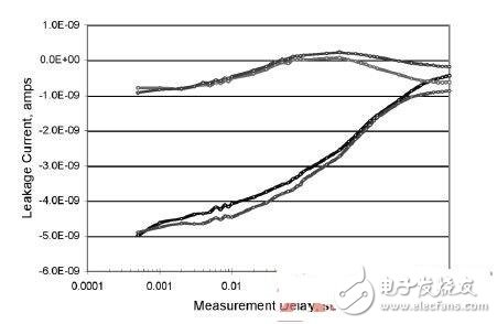
In order to obtain a stable and repeatable measurement, the key point is that the measured parameter is reached and maintained at a stable value during the source/measurement period. This concept is especially important for OLED testing. The electrical and optical properties of OLEDs are time dependent and exhibit hysteresis effects. 1,2 The electrical properties of OLEDs are very different compared to more familiar semiconductor based photoemitters. For this reason, we must have a complete understanding of the transient behavior of test parameters before attempting to design and implement an automated test system. The characteristics of the transient process also contribute to the development of test protocols, and simplify the analysis of test data and increase the credibility of the test system. The source delay time, that is, the variable time delay from applying the signal to the OLED to the beginning of the measurement, may be used to reduce transient effects. Figure 1 shows the leakage current for each pixel when four-pixel simultaneous test is performed with the test system set to NPLC = 10 and the signal source delay from 0.0005 to 10 seconds. In order to achieve a steady state leakage current of less than 1 nA, it takes at least a few seconds.

Figure 1. Reverse bias current for each pixel during a four-pixel test where the source/measurement time delay varies from 0.0005 to 10 seconds using a 6V bias.
The test performance of a test system depends on the basic accuracy of the test instrument and the sources of error caused by other components in the system. The leakage current of the cable and switch card is an error source for current measurement. For test fixtures and cable connections, this error increases as the absolute value of the measured current decreases. Choosing the right scan card means that the scan card's rated leakage current is at least an order of magnitude lower than the minimum measured current. This is a critical indicator. For test systems designed to perform 10-8A measurements with 2400, no protection circuitry is required.
The voltage measurement error of the two-wire sensed structure is caused by the "on" resistance of the relay used on the scan card and the resistance drop of the cable. The two relays on the 7015-C card will combine to produce a maximum "300Ω resistance to the signal path. For current measurements less than 50μA, the voltage error, including typical resistive voltage drop losses, will be small, with a typical value of 15μV. For larger current measurements, such as when an entire column of the display is energized, the error will be proportional to the current of the OLED. This value may be calculated using Verror = 2 * (Rrelay) & TImes; IOLED(s). For applications that require very high voltage measurement accuracy, that is, voltage measurements are not affected by DUT current, a four-wire test structure is required.
The mechanical relays on the 7158 and 7058 types of scanning cards have a contact resistance of approximately 1 Ω or less, and the resulting voltage error is negligible, even at high currents. For this application, the errors caused by the contact potential of the following scanning cards may also be considered negligible; the contact potential of these scanning cards is: 7015-C is "5mV, 7058 and 7158 are respectively 250μV and "200μV.
Optical Rotary Sensor,Custom Encoder,Optical Encoder 6Mm Shaft,Handwheel Pulse Generator
Jilin Lander Intelligent Technology Co., Ltd , https://www.jilinlandermotor.com