In recent years, the problem of energy shortage has become increasingly prominent. People are worried about the exhaustion of energy, but the waste of energy is surprisingly large. For example, various discarded batteries, especially those used in remote-controlled toy cars, have been discarded even without using half of their energy, which not only causes waste of energy, but also causes environmental pollution. Therefore, it is urgent to develop a device for collecting energy of various used batteries.
This paper designs a power collection device with DC power converter as the core. This device can be used for people to charge mobile phones at any time during the journey, and can also be used for miner lighting. The charger delivers the power of a DC power source to a rechargeable battery of 3.6 V or higher. The system uses MC34063 and HT7750 to build the power supply circuit to charge the battery according to the input voltage. After the 89C51 single-chip microcomputer controls the AD0832 to detect the output voltage of the power supply, it can judge whether the battery is charged, and the detection time can be set according to the needs of the user. Set and display it through the digital tube. In order to improve the working efficiency of the single chip microcomputer, the single chip is in the dormant and working state for intermittent detection.
1. System design block diagram
The core of the power collection charger is a DC power converter, and the energy absorbed from the DC power source is transferred to the rechargeable battery. The power collection charger delivers the input power as much as possible to the device to be charged, so that the charging efficiency of the charger is as high as possible. The charger has low input voltage requirements and can absorb the energy in the DC power supply as much as possible, which is more energy efficient than the general charger. The system block diagram is shown in Figure 1.
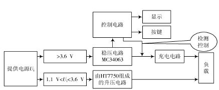
Figure 1 system block diagram
According to the value of the voltage Ui, two DC power converters are used. When the voltage is 1.1 V "Ui "3.6 V, the Boost boost circuit composed of HT7750 is used; when the power supply is greater than 3.6 V, the circuit is a single-chip microcomputer. Control integrated chip MC34063 to achieve. The MC34063 operates from 3 to 40 V, so the power supply input voltage needs to be above 3 V to allow it to operate. The single-chip microcomputer can improve the efficiency by self-sleeping, and can also detect the voltage value to control the charging of the battery, and the digital tube displays the length of the detection time, which can be arbitrarily adjusted according to the requirements of the user. Such a circuit is intuitive, stable, and reliable, and in practical use, it can stably reach the required current value and voltage value under the condition of load. At the same time, the circuit is simple and easy to understand, easy to debug data, and has a high success rate.
2. Hardware circuit design
2.1 boost circuit design
The boost circuit is mainly composed of HT7750, which has high efficiency and low ripple. This series features ultra-low startup voltage and high output voltage accuracy. Only three external components, namely inductor, Zener, and electrolytic capacitor, are required to provide a fixed output of 5 V. The circuit is shown in Figure 2.
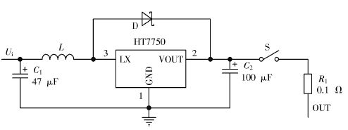
Figure 2 boost circuit
2.2 Power supply circuit design
The power supply circuit is a voltage regulator circuit composed of MC34063 chip. This chip is a switching regulator power supply chip with PWM regulation mode that can be step-down or boostable. The MC34063 has a working voltage range of 3~40 V. This circuit The input voltage is regulated to the required voltage, and this voltage can also be used as the operating voltage of the microcontroller and ADC0832. The circuit structure is shown in Figure 3.
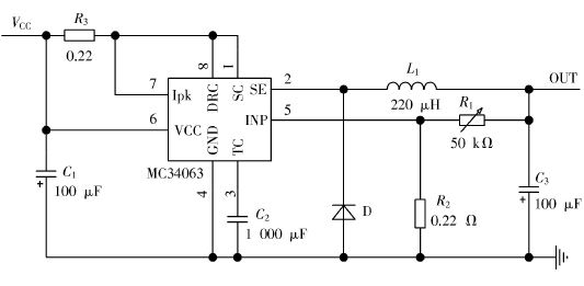
Figure 3 power supply circuit
2.3 Control circuit design
Using 8051 single-chip microcomputer, it has the advantages of flexible programming, powerful function and low cost. Compared with INTEL's 8096 series 16-bit single-chip microcomputer, the 8051 has obvious price advantage. At the same time, it can meet the needs and become the first choice. It can sleep itself to reduce power consumption and improve efficiency. It is powered by a stable 5 V voltage output from the reference power supply circuit, mainly to control the voltage. The 89C51 single-chip microcomputer controls the AD0832 to detect the magnitude of the output voltage of the power supply, thereby judging whether the battery is charged, and the length of the detection time can be set according to the needs of the user, and displayed through the digital tube. The ADC used here is the ADC0832 chip, which is a serial ADC with speed and accuracy sufficient for this circuit. The VCC pin of the ADC0832 is indirectly connected with a large capacitor of the reference circuit to input the voltage to the ADC0832. more stable. The circuit structure is shown in Figure 4.
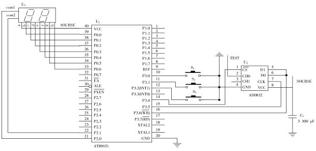
Figure 4 control circuit
2.4 Charging circuit design
The circuit controls the charging circuit through the single-chip microcomputer to realize charging of the battery and plays a switching role. And an LED light is added to the circuit to indicate whether the charger is working. The circuit is shown in Figure 5.
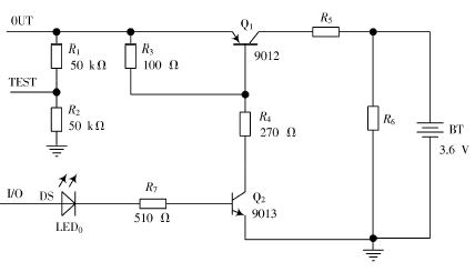
Figure 5 charging circuit
3. Design of the software part
The software of this system is written in C language, and all the code is compiled and debugged under UV2. The software program design mainly detects the magnitude of the power supply output voltage, so as to judge whether to charge the battery, and at the same time, the single chip microcomputer reduces power consumption and improves efficiency by sleeping itself. The main flow chart of the program is shown in Figure 6, and the sleep time control flow chart is shown in Figure 7.
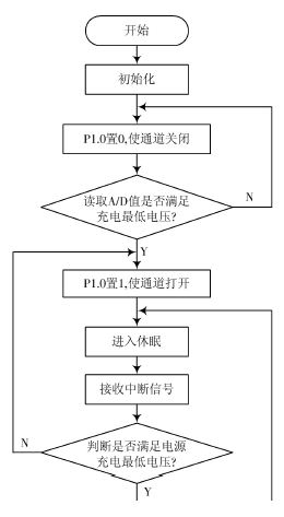
Figure 6 main flow chart
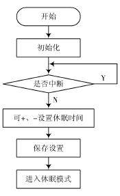
Figure 7 sleep time control flow chart
4 Test methods and results
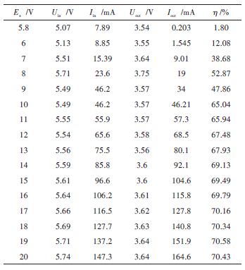
(1) When the input voltage Ui is 10~20 V, the internal resistance Rs of the power supply is 100 Ω, and the internal resistance Rc of the rechargeable battery is 0.1 Ω, which is calculated theoretically:
Ic > (Es - Ec) (Rs + Rc)
which is:
Ic > (20 - 3.6) (100 + 0.1) = 163.8 mA
In the actual measurement, Ic = 164.6 mA" 163.8 mA, which meets the design requirements. The test data is shown in Table 1.
The efficiency of this design is the product of the output voltage U*out and the output current Iout as the product of the input voltage Uin and the current Iin. which is:
η = (Uout*Iout ) (Uin*Iin )
(2) When Ui gradually rises from 0, the Ui that can start the charging function is 0.28 V; when Ui is 0, the maximum reverse charging current of the system is only 0.09 mA.
Table 1 High voltage parameter table
5 Conclusion
This paper designs and implements a DC-based power collection charger based on single-chip microcomputer. The charger can still transfer energy to a rechargeable battery of 3.6 V or higher with an input voltage as low as 1 V. At the same time, the experimental prototype was made and the experimental prototype was tested. The experimental results show that the charger has the advantages of wide operating voltage range, high efficiency, strong adaptability and good reliability. To a certain extent, it has solved the waste of waste battery energy and environmental pollution.
Submersible cable is a type of cable designed for use in underwater environments, such as in offshore oil and gas exploration, marine research, and underwater construction. These cables are typically made of materials that are resistant to corrosion, abrasion, and water damage, and are designed to withstand high pressures and temperatures.
Submersible cables are used to transmit power and data signals between underwater equipment and control systems on the surface. They may also be used to connect sensors and other monitoring devices to data acquisition systems.
The construction of submersible cables can vary depending on the application and the environment in which they will be used. Some cables may be armored with steel or other materials to provide additional protection against damage from rocks and other debris. Others may be coated with special materials to resist chemical corrosion or to improve their electrical conductivity.
Overall, submersible cables are essential components of many underwater applications, and their reliability and durability are critical to the success of these operations.
Submersible Electrical Pump Cable,Submersible Flat Cable,Flat Submersible Pump Cable,Waterproof Cable Rubber,Submersible Electrical Cable
Ruitian Cable CO.,LTD. , https://www.hbruitiancable.com