At present, single-chip microcomputers have been widely used in electronic products. Many types of single-chip microcomputers have A/D conversion circuits inside, but such single-chip microcomputers will cost a few yuan or more in price than single-chip microcomputers without A/D conversion function. We provide a practical A/D conversion circuit realized by a common single-chip microcomputer. It only needs to use two I/O pins of an ordinary single-chip microcomputer and one operational amplifier, and it can be easily expanded to have 4 Channel A/D conversion function, because it occupies very little resources, has low cost, and its A/D conversion precision can reach 8 bits or higher, so it is very practical.
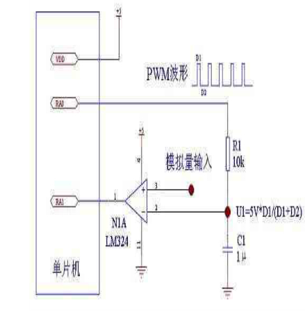
Its circuit is shown in Figure 1:

Figure 1
Its working principle is as follows:
1, hardware description:
In Figure 1, “RA0†and “RA1†are the two I/O pins of the MCU, which are set to the output and input states respectively. When A/D conversion is performed, PWM is generated by software in the program and sent by RA0 pin. The PWM waveform of the preset duty cycle. The RA1 pin is used to detect the state of the comparator output.
R1 and C1 form a filter circuit for smoothing the PWM waveform sent from the RA0 pin. The PWM waveform output by RA0 is filtered by R1 and C1 and delayed, and a stable voltage value is generated at U1. The voltage value U1=VDD*D1/(D1+D2), if the operating voltage of the MCU is stable +5V, Then U1=5V*D1/(D1+D2).
The LM324 in Figure 1 is used as a comparator. The U1 voltage at the input negative terminal is compared with the analog voltage value at the input positive terminal. When U1 is greater than the analog input voltage, the output of the comparator is low, and vice versa. level.
2, A / D conversion process:
If RA0 is outputted to the PWM waveform and its duty cycle changes gradually from small to large, the voltage of U1 will gradually change from small to large. When the U1 voltage exceeds the measured voltage, the output of the comparator changes from high level. Low level, so it can be considered that the analog quantity measured at the moment of the change is equal to the voltage of U1.
Since the voltage value of U1 = VDD * D1/ (D1 + D2), when VDD is fixed, its voltage value depends on the duty cycle of the PWM waveform, and the duty cycle of the PWM is used by the microcontroller software to control the PWM output. The value determines if the software uses an 8-bit register A to store the duty cycle value D1 of the PWM output of RA0. Therefore, when RA1 detects that the value of "1" is changed to "0", the value D1 of the A register is The A/D conversion value of the measured voltage has an A/D conversion result of 8 bits. If a 16-bit register is used as the duty cycle of the output PWM, the A/D conversion value can reach 16 bits.
3, A / D conversion error analysis and solutions:
The error of A/D conversion is mainly determined by the following aspects, which are as follows:
(1) Power supply voltage VDD of the MCU: In this A/D conversion, the VDD voltage is the main cause of the A/D conversion error. If the VDD voltage accuracy is made higher, the A/D conversion error can be very high. Small, the actual A/D conversion error is less than 1% with VDD voltage accuracy of 0.5%.
(2) Software generated PWM duty cycle: If the software used to generate the PWM is poorly designed, the register value that stores the duty cycle will be inconsistent with the actual output PWM duty cycle, which will cause measurement errors.
(3) Offset voltage at the input of the comparator: This voltage has a certain influence on the A/D conversion accuracy, but the effect is small.
(4) Ripple of RC filter circuit: When R1 and C1 are improperly valued, the voltage ripple at U1 is large, and the delay time is not enough, which will cause error in A/D conversion. Therefore, R1 and C1 are taken. The value should not be too small, but too large will affect the A/D conversion speed. It is recommended to use the R1 and C1 parameters shown in Figure 1. In the case of reasonable ripple, the conversion error can also be eliminated by software.
A/D conversion error solution:
(1) The error caused by VDD can only be solved by increasing the accuracy of the VDD voltage, which is equivalent to the reference voltage for A/D conversion.
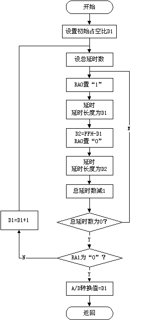
(2) For the error caused by poor PWM design in software, the software can be modified to solve the problem. This article provides a program flow chart for generating PWM by software. In actual use, the program can be designed according to this process.
(3) The error caused by the ripple of the comparator and RC filter circuit can be eliminated by the upper and lower detection methods in software, that is, the duty cycle of the PWM is changed from small to large, so that the U1 voltage is low. The gradual change is high, the A/D conversion value is recorded when the output of the comparator changes, and the duty cycle of the PWM is changed from large to small, so that the U1 voltage changes from high to low, and the comparator output is recorded when the output changes. The A/D conversion value averages the two A/D conversion values ​​to effectively eliminate both errors.
(4) Digitally filter the A/D conversion value, such as averaging multiple conversions. There are many ways to eliminate errors by digital filtering, and will not be described here.
4, A / D conversion speed and improvement methods:
Since the A/D conversion is completed by PWM filtering and then compared, the PWM generation and filtering require a certain time, so the A/D conversion speed is slow, which is suitable for the A/D conversion speed requirement. In high products, the A/D conversion speed depends on the following aspects:
(1) The running speed of the single-chip microcomputer: the higher the running speed of the single-chip microcomputer, the higher the frequency of the PWM, the smaller the RC value can be obtained, the shorter the delay time, and the faster the conversion speed.
(2) The magnitude of the measured voltage value: Since the U1 voltage is gradually increased from small to large, when the measured voltage value is small, the time when the U1 voltage rises to the corresponding value is shorter, and the A/D conversion is completed. The faster the speed.
(3) Initial duty cycle: The higher the initial duty cycle, the higher the U1 voltage, the shorter the time it rises to the measured voltage value, and the faster the A/D conversion is completed.
As mentioned above, the speed of the A/D conversion can be increased by increasing the operating frequency of the microcontroller and setting a higher initial duty cycle value as much as possible when predicting the measured voltage range, if the required A/D is required. The conversion accuracy is not high, and the delay time of the PWM output can be shortened in the software to increase the A/D conversion speed. If the microcontroller has an external level shift interrupt and a timer interrupt, the accuracy and speed of the A/D conversion can be improved.
5. Measurement range of input voltage:
The input voltage measurement range of A/D conversion is 0V to the power supply voltage (VDD) of the MCU. If it is necessary to increase the voltage range to be measured, the input voltage can be measured by voltage divider, but the error of A/D conversion will be affected. The effect of the voltage divider resistor.
6, multi-channel expansion of A / D conversion channel:
The operational amplifier used in the figure is LM324. The integrated circuit has four op amps inside. The input terminals of the other three op amps can be used as another three A/D conversion channels. The output is connected to the MCU. With a slight modification, 4-way A/D conversion can be realized without increasing the cost.
7, using the same working principle to achieve D / A conversion:
As shown in Figure 2, the circuit can easily implement the D/A conversion function using only one I/O pin of the microcontroller. Its output analog voltage Vout = VDD * D1/ (D1 + D2). The output voltage is rippled, and when the RC value is large enough, the ripple value is almost zero and can be ignored.

Figure II
8, single-chip A / D conversion software program flow chart:

Electric Two And Three Wheelers Battery
Electric Two And Three Wheelers Battery,Electric Motorcycle Lifepo4 Battery,Lifepo4 Battery For 2 Wheeler,23Ah Lifepo4 Battery For 2 Wheeler
JIANGMEN RONDA LITHIUM BATTERY CO., LTD. , https://www.ronda-battery.com