Abstract: The design of the acquisition node of the parking current using AD574A combined with software is proposed. The node uses SJA1000 CAN transceiver to effectively realize the transmission of vehicle speed information to the central control ECU via CAN bus. The simulation analysis experiment (or frame experiment) proves that the current acquisition can accurately complete the acquisition of the parking current and realize the information transmission based on the CAN bus.
This article refers to the address: http://
Key words: electronic parking system; CAN bus; current acquisition; central control node
The Electronic Parking Brake System (EPB) refers to a technology that integrates temporary braking during driving and long-term braking after parking, and implements parking braking electronically. In order to be able to obtain the theoretical parking pressure applied by each vehicle, and monitor the working state of each vehicle integrated actuator, prevent the parking motor from working for a long time in a large current state, and prevent the parking motor from overheating and burning, the EPB is generally equipped with a station. The vehicle current collecting node sends the parking current to the central control node (ECU) via the CAN bus. This paper mainly introduces the interface setting, acquisition method and software design of the parking current collecting node based on AD574A.
1 system hardware design
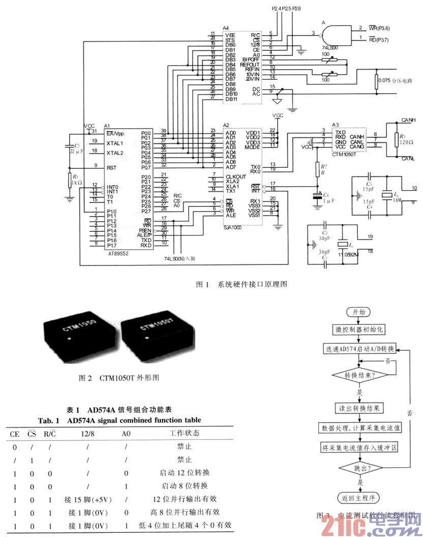
The hardware circuit design of the parking current collecting node includes two parts: CAN bus communication circuit design and vehicle speed acquisition circuit design, as shown in Figure 1.
1) CAN bus communication circuit design
When designing the CAN bus communication circuit, the CAN controller uses the CTM1050T (see Figure 2) produced by Guangzhou Zhiyuan Electronics Co., Ltd., and the microcontroller uses the AT89S52.
2) Current acquisition hardware design
The current sampling is carried out by the AD574A, which is a 12-bit high-speed successive approximation analog-to-digital converter produced by American AD Company, which is very suitable for the use of high-precision fast sampling system. For the collection of the parking current, in order to control the direction of rotation of the motor, the direction of the parking current is variable, so the AD574A bipolar input is used to divide the output into 8 bits and 4 bits. The signal combination function of AD574A is shown in Table 1.
According to the signal combination function table of AD574A, AD574A has two port selection addresses, which are distinguished by A0. As shown in Figure 1, a write to the external address 0x8fff can initiate a 12-bit A/D conversion, while a read 0x9fff address can read a high 8-bit digital output, and a read address of 0xdfff can read a lower 4-bit digital output. The signal to be measured is introduced by pins 13 and 9. In the connection process of the circuit, the analog ground and the digital ground, that is, the 9 and 15 feet must be common, otherwise the conversion cannot be completed. Two 100 ohm potentiometers connected to pins 12 and 10 of the AD574A are used to adjust the zero and full scale of the chip. First, the input voltage should also be -5 V. At this time, adjust the potentiometer of the 12-pin of the chip. R2, so that the output digital quantity after the conversion jumps between 0000H and 0001H; then let the input voltage be +5 V. At this time, adjust the potentiometer R1 connected to the pin 10 of the chip and measure the voltage across the voltage dividing resistor so that the converted output number The amount jumps between 0FFEH and 0PPFH. One important point to note when designing the hardware circuit is that the data output line of the AD574A and the data bus of the MCU should be connected to the high-order 8-bit DB4 to B11 to the D0 to D7 of the data bus, and the lower 4-bit DB0 to DB3 are connected to the data. The upper 4 bits of the bus are D4 to D7. If you make a mistake, you can't read the correct conversion result, and it is easy to burn the chip.

The hardware system obtains the real-time current value by the single-chip operation after the voltage divider resistor is serially connected in the circuit and then the measurement terminal voltage is converted into a digital signal. However, since the maximum operating current of the parking brake is 25 A, the resistance of the voltage dividing resistor must be small to ensure that it is not burnt, so the system uses a resistance of 0.007 5 Ω.
2 system software design
1) Parking current acquisition software design
In view of the aforementioned method of collecting the parking current, according to the interface design and timing requirements, the system designs the parking current collecting node based on the method. The main program flow chart of the parking current collection is shown in Fig. 3.
2) CAN bus ECU data receiving design
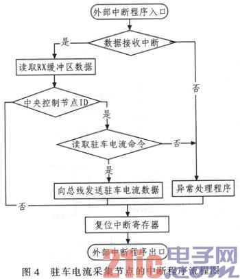
The central control node uses the timer 0 interrupt according to the defined communication mechanism to periodically read the collected parking current data frame sent to the CAN bus. After receiving the frame, each parameter collection node returns the collection information in the buffer of the node to the central control node according to the defined priority. After receiving the return information of the parameter collection node, the central control node updates the data in the buffer. Figure 4 is a flow chart of the interrupt routine of the parking current collecting node.

3 system simulation experiment
Due to the constraints of the experimental conditions, the system simulation experiment (automobile bench test) was carried out before the pulse value of the vehicle speed sensor could not be obtained in the form of a real vehicle experiment. During the test, the motor is used to drive the load, simulate the changing parking brake current, and verify the correctness of current collection by returning data.
The CAN bus is debugged by the PC host computer through the CAN232B intelligent PC-CAN bus interface card. GY8501 CAN232B intelligent PC-CAN bus interface card is an intelligent CAN bus interface card with 1 CAN interface and one RS232 interface, which can transmit in both directions. The interface card can be used as a standard CAN node and is a powerful tool for CAN bus product development, CAN bus device testing, and data analysis. In the CAN232B device, the CAN bus circuit adopts an independent DCDC power supply module, and the photoelectric spacer has strong anti-interference ability, which ensures the reliability and anti-interference of the test. CAN232B products can be directly configured, sent and received by the CAN bus using the CANTools tool software provided by the manufacturer.
By debugging the designed CAN bus-based electronic parking current collecting node, the node can work normally, the parameters are collected accurately, the CAN bus sends and receives the message correctly, and the expected design function is realized.
4 Conclusion
The test results show that the system can collect the parking current in real time and control the relevant parking system. The application of the system extends the service life of the electronic parking brake system, making the electronic parking system more energy efficient and economical.
The Micro Inverter, or MI, is a compact and intelligent device that converts direct current (DC) generated by solar panels into alternating current (AC) for immediate use. Unlike traditional string inverters, which convert the entire array's DC power, the MI operates on a per-panel basis. This means that each solar panel operates independently, optimizing energy production and ensuring maximum output even under partial shading or panel malfunctions.
One of the key advantages of the MI is its scalability. Whether you have a small residential installation or a large commercial project, the MI can be easily integrated into any solar power system. Its modular design allows for easy expansion, making it a flexible choice for future upgrades or additions.
Efficiency is at the core of the MI's design. By minimizing power losses and maximizing energy production, it ensures that you get the most out of your solar panels. With its advanced MPPT (Maximum Power Point Tracking) technology, the MI constantly adjusts the panel's operating voltage and current to extract the maximum power available. This not only increases energy yield but also extends the lifespan of the solar panels.
In addition to its exceptional performance, the MI offers unmatched safety features. With its built-in isolation transformers, it provides electrical isolation between the solar panels and the grid, eliminating the risk of electric shock. It also boasts advanced monitoring capabilities, allowing you to track the performance of each individual panel in real-time, ensuring optimal operation and maintenance.
Micro Inverter,Micro Solar Inverter,On-Grid Pv Inverter,Solar Charge Controller Mppt
Bosin Power Limited , https://www.bosinsolar.com