With the rapid development of computer technology, the use of USB mobile storage devices has become very common. Therefore, chips that use USB mobile storage device interfaces on some devices and instruments that need to transfer data have been produced one after another. CH375 is one of them. It is a universal interface chip of USB bus, supporting HOST host mode and SLAVE device mode.
This article refers to the address: http://
At the local end, the CH375 has an 8-bit data bus and read, write, chip select control lines and interrupt outputs, which can be easily hooked up to the system bus of the microcontroller/DSP/MCU controller. In the USB host mode, the CH375 also provides serial communication mode, which is connected to the MCU/DSP/MCU through serial input, serial output and interrupt output. The USB host mode of the CH375 supports various commonly used USB full-speed devices. The external MCU/DSP/MCU can communicate with the USB device through the CH375 according to the corresponding USB protocol.
CH375 chip internal structure
1 internal structure
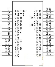
The CH375 chip integrates a PLL frequency multiplier, a master-slave USB interface SIE, a data buffer, a passive parallel interface, an asynchronous serial interface, a command interpreter, a protocol processor for controlling transmission, and a general firmware program. The pin arrangement of the CH375 chip is shown in Figure 1.

â–² Figure 1 CH375 chip pinout
2 internal physical endpoints
The CH375 chip has seven physical endpoints inside. Endpoint 0 is the default endpoint and supports uploading and downlinking. The upload and downlink buffers are each 8B. Endpoint 1 includes the uploading endpoint and the downstream endpoint. The upload and downlink buffers are each 8B, and the endpoint of the uploading endpoint is 81H. The endpoint number of the downstream endpoint is 01H; the endpoint 2 includes the upload endpoint and the downstream endpoint, the upload and downlink buffers are each 64B, the endpoint number of the upload endpoint is 82H, and the endpoint number of the downstream endpoint is 02H.
The host endpoint includes an output endpoint and an input endpoint. The output and input buffers are each 64B. The host endpoint uses the same set of buffers as endpoint 2. The output buffer of the host endpoint is the upload buffer of endpoint 2, and the input buffer of the host endpoint is The downstream buffer of endpoint 2.
Among them, endpoint 0, endpoint 1, and endpoint 2 of CH375 are only used in the USB device mode, and only the host endpoint is needed in the USB host mode.
Software interface
For the application of USB storage device, CH375 directly provides the read/write interface of the data block, and uses 512b physical sector as the basic read/write unit, thus simplifying the USB storage device into an external data storage. The MCU can freely read and write USB storage. The data in the device can also be freely defined in its data structure.
CH375 provides a file-level interface for USB storage devices in the C language subroutine. These application layer interface APIs contain common file-level operations that can be ported and embedded into a variety of commonly used microcontroller programs.
The CH375 U disk file-level subroutine library has the following features: support common FAT12, FAT16 and FAT32 file systems, disk capacity up to 100GB, support multi-level subdirectories, support 8.3 format uppercase letter file names, support file open, New, delete, read and write, search, etc.
The file-level interface API subroutine of CH375 requires approximately 600b of random access RAM as a buffer. All APIs return after the call, but there is not necessarily a response data. Please refer to the CH375 data sheet for a description of the API parameters.
Circuit diagram of CH375 in MCU read and write U disk
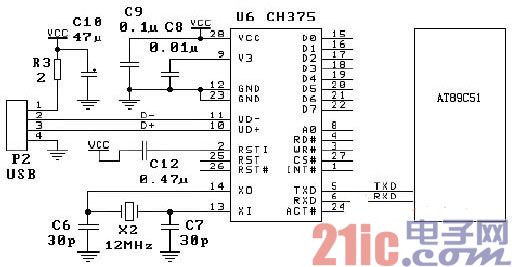
Figure 2 shows the circuit schematic of the MCS-51 microcontroller reading and writing U disk. If the TXD pin of the CH375 chip is left floating or not grounded through the lower resistor, the CH375 works in the serial port mode. In the serial port mode, the CH375 only needs to connect three signal lines with the MCU/DSP/MCU, the TXD pin, the RXD pin and the INT# pin. All other pins can be left floating. Except for fewer connection lines, other peripheral circuits are basically the same as parallel ports. Since the INT# pin and the TXD pin can only provide a weak high-level output current during the CH375 reset period, the MCU may operate incorrectly in order to avoid interference of INT# or TXD during CH375 reset during long-distance connection. A pull-up resistor with a resistance of 1 to 5kΩ can be added to the INT# pin or the TXD pin to maintain a stable high level. After the CH375 chip reset is completed, the INT# pin and the TXD pin will be able to provide a 5mA high-level output current or a 5mA low-level sink current.

Figure 2 MCS-51 microcontroller read and write U disk circuit schematic
The interface of the single chip to read and write the U disk
Since the CH375 has built-in firmware for handling the dedicated communication protocol of the Mass-Storage mass storage device, the embedded system's MCU can use the CH375 as a removable large-capacity memory via the USB flash drive (USB flash drive, USB external hard drive). Data reading and writing requires only a few instructions, without the need to learn more about the USB communication protocol. If the embedded system needs to organize the USB storage device into a file system, the interface API provided by the CH375 file-level subroutine library can be directly called, and the file system is processed by the subroutine library.
CH375 host USB-HOST circuit design considerations
Some USB devices often have the following problems when they are plugged in:
â— CH375 reset or microcontroller reset (especially the microcontroller system using uP monitoring circuit).
â— CH375 or MCU suddenly works abnormally and loses control.
â— The operating current of the CH375 chip suddenly increases and continues to do so.
The following solutions can be found when the above problems occur:
â— Power the USB socket separately, so that even if the USB device is plugged in, there is a capacitor charging process that will not affect the microcontroller and CH375. The workaround is to pass the 5V main power supply through two independent current limiting inductors (or separate the power lines in the PCB), one set to CH375 and one MCU, and the other set to the USB socket.
◠Connect a current limiting resistor or inductor in series with the USB socket and connect the electrolytic capacitors for energy storage in parallel with the USB socket power supply. If the inductor is used, it can also limit the sudden change of the current to prevent the power supply voltage from dropping. However, after the USB device is pulled out by the inductor, it is easy to generate an overshoot high voltage in the USB socket, so the storage capacitor must be connected. (Note that the current limiter R1 of the USB socket has been marked as 1Ω in the schematic of the first version of the CH375 evaluation board. It is recommended to replace it with a 5Ω resistor or fuse resistor.)
â— Other temporary solutions (not recommended): 1 Add a USB extension cable between the USB device and the USB socket. 2 Parallel large storage capacitors on the main power supply to provide sufficient instantaneous power when the U disk is inserted, reducing the impact on the power supply voltage.
â— Refer to current computer-side solutions: The power supply to the USB port is provided by a fuse or current-limiting inductor that limits the instantaneous current. For the USB port on the front panel of the computer, since it has a long connection wire, it naturally weakens the influence on the main power supply, and the 5V power supply of the computer is very large, and the continuous supply current is above 20A, so it is not easily affected.
Connector 2.00Mm Pitch,Ph Connector Accessories,Ph Connectors Accessories,Strip Wire Connectors
YUEQING WEIMAI ELECTRONICS CO.,LTD , https://www.weimaicarconn.com