Overview:
This paper presents a push-pull inverter vehicle switching power supply circuit design. Based on the push-pull inverter-high-frequency transformer-full-bridge rectification design, the scheme uses a DC-DC converter with 24VDC input-220VDC output and rated output power of 600W, and adopts the AP method to design a high-frequency push-pull. transformer. Finally, it is proved by experiments that the push-pull transformer designed by this scheme is especially suitable for medium and small power applications with low voltage and high current input, and the expected effect is achieved.
0 Introduction With the increase in the variety of modern automotive electrical equipment, the increase in power levels, the need for more and more types of power, including AC power and DC power. These power supplies need to use switching converters to provide +12VDC or The DC voltage of +24VDC is upgraded to +220VDC or +240VDC through the DC-DC converter, and the latter stage is converted into a commercial frequency AC power supply or a variable frequency voltage regulating power supply through a DC-AC converter. For the pre-stage DC-DC converter, the high-frequency DC-AC inverter part, the high-frequency transformer and the AC-DC rectification part are included, and different combinations are adapted to different output power levels, and the conversion performance is also different.
Push-pull inverter circuit has been widely used due to its simple structure and high utilization of transformer core, especially in low- and high-current input medium and small power applications. At the same time, full-bridge rectifier circuit also has high voltage utilization and support output power. Higher characteristics. In view of this, this paper proposes a push-pull inverter vehicle switching power supply circuit design. Based on the push-pull inverter-high-frequency transformer-full-bridge rectification design, the scheme further designs a DC-DC converter with 24VDC input-220VDC output and rated output power of 600W, and uses the AP method to design the corresponding push-pull transformer. .
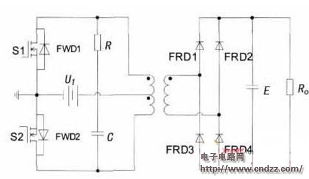
1 Working principle of push-pull inverter Figure 1 shows the basic circuit topology of push-pull inverter-high frequency transformer-full-bridge rectifier DC-DC converter. By controlling the two switching tubes S1 and S2 to be alternately turned on at the same switching frequency, and the duty ratio d of each switching tube is less than 50%, a certain dead time is left to avoid simultaneous conduction of S1 and S2. The front-stage push-pull inverter inverts the input DC low voltage into an AC high-frequency low voltage, sends it to the primary side of the high-frequency transformer, and couples it through the transformer to obtain the AC high-frequency high voltage on the secondary side, and then passes the reverse fast The full bridge is rectified and filtered by the recovery diode FRD to obtain the desired DC high voltage. Since the back pressure that the switch can withstand is at least twice the input voltage, that is, 2UI, and the current is the rated current, the push-pull circuit is generally used in low- and medium-power applications where the input voltage is low. 
Figure 1: Overall topology of the scheme design. When S1 is turned on, its drain-source voltage uDS1 is only the turn-on voltage drop of a switching transistor. In the ideal case, uDS1=0 can be assumed, and an induced voltage is generated in the winding. And according to the same name end relationship of the primary winding of the transformer, the induced voltage is also superimposed on the off S2, so that the voltage that S2 receives when turned off is the sum of the input voltage and the induced voltage is about 2 UI. In practice, the transformer The leakage inductance produces a large spike voltage applied across S2, causing large turn-off losses. The efficiency of the converter is not very high due to the leakage inductance of the transformer. An RC snubber circuit, also called an snubber circuit, is connected between the drains of S1 and S2 to suppress the generation of spike voltage. And in order to provide feedback loop for energy feedback, the freewheeling diode FWD is anti-parallel on both ends of S1 and S2.
(Please read the PDF for details)
Multicore Silicone Cable,Insulated Wire,Insulated Silicone Cable,Oil Proof Silicone Wire
JIANGSU PENGSHEN HIGH TEMPERATURE WIRE CABLE CO., LTD. , https://www.pengshencable.com