The functions of each pin are as follows: 1 pin: external power supply negative terminal VSS or ground, normally grounded. 8 feet: external power supply VCC, the range of the bipolar time base circuit VCC is 4.5~16V, and the range of the CMOS type time base circuit VCC is 3 ~ 18V. Generally use 5V. 3 feet: output terminal V. 2 feet: low trigger end. 6 feet: TH high trigger end. 4 feet: It is the direct clearing end. When the termination is low, the time base circuit does not work. 5 feet: VC is the control voltage terminal. If the external voltage is connected to this terminal, the reference voltage of the two internal comparators can be changed. When the terminal is not used, the terminal should be connected to a 0.01μF capacitor to ground to prevent interference. 7 feet: discharge end. This terminal is connected to the collector of the discharge tube and is used as a discharge of the capacitor when the timer is used.
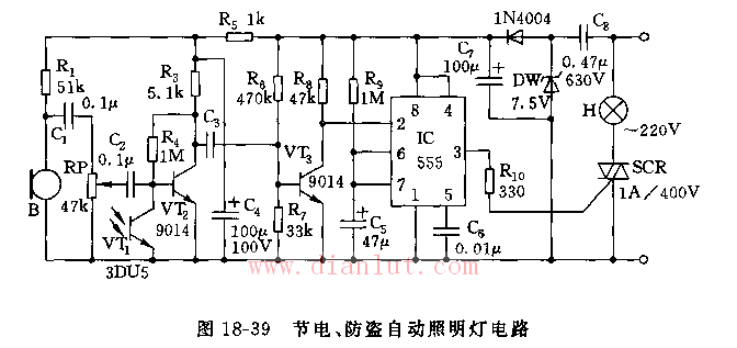
As shown in the figure, the circuit consists of a capacitor step-down rectifier circuit, an acoustic and optical sensing electronic switch, and a one-shot delay circuit.
The buck rectifier circuit generates a voltage of VDD=7V as a voltage source. Microphone pickups and phototransistors 3DU5 and VT2, VT3 act as sensing electronic switches. During the daytime, the photosensitive tube is in a low-resistance state due to illumination, VT2 is cut off, and the pickup signal cannot be amplified; at night, 3DU5 is high-resistance, VT2 is turned on, and the signal picked up by B is amplified by VT2 and VT3, triggered by 555 and R9. The one-shot delay circuit composed of C5 sets 555 to generate a high-level pulse width of td=1.1R9C5, so that the SCR triggers the conduction and the light is on. After the timing td, the light is off. The delay of the illustrated parameters is approximately 100 seconds.
This circuit can be used as a delay switch for the upper and lower corridors, and can also be used for the anti-theft switch in a quiet place.

Spin Motor,Mini Spin Motor,Washing Machine Spin Motor,Automatic Wash Motor
WUJIANG JINLONG ELECTRIC APPLIANCE CO., LTD , https://www.jinlongmotor.com