Usually, the switches used for the buttons are mechanical elastic switches. When the mechanical contacts are opened and closed, due to the elastic action of the mechanical contacts, a push button switch does not immediately turn on when closed, nor does it open when disconnected. It will be completely disconnected at once, but with a series of jitters at the moment of closing and disconnecting, as shown in Figure 8-10.
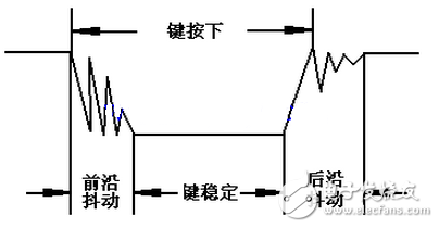
Figure 8-10 Button jitter status diagram
The length of the button's stable closing time is determined by the operator. It usually takes more than 100ms. If you press it quickly, it will reach 40-50ms, which is difficult to lower. The jitter time is determined by the mechanical characteristics of the button, and is generally within 10ms. In order to ensure that the program responds to the button once or once, it must respond to the debounce. When a change in the state of the button is detected, the action is not immediately responded to, but the process is waited for the closure or disconnection. Button debounce can be divided into hardware debounce and software debounce.
Hardware debounce is to connect a capacitor in parallel with the button. As shown in Figure 8-11, the charge and discharge characteristics of the capacitor are used to smooth the voltage glitch generated during the jitter process to achieve debounce. However, in practical applications, the effect of this method is often not very good, but also increases the cost and circuit complexity, so there is not much used in practice.
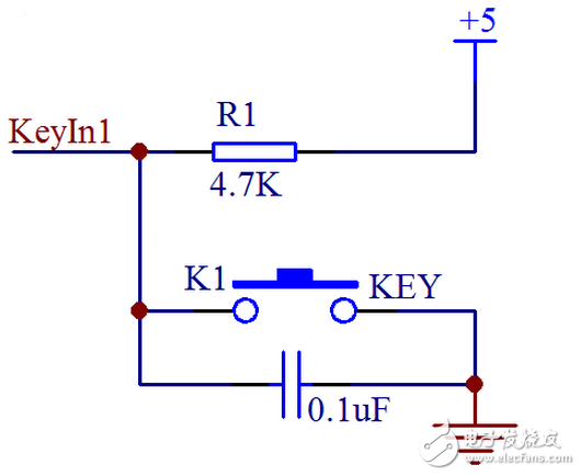
Figure 8-11 Hardware Capacitance Debounce
In the vast majority of cases, we use software or programs to achieve debounce. The simplest debounce principle is to wait for a delay time of about 10ms after detecting the change of the button state, and then perform the button state detection after the jitter disappears. If the state is the same as the state just detected, the button can be confirmed. The action has been stabilized. The previous program is slightly modified to get a new program with debounce function as follows.#include
Sbit ADDR0 = P1^0;
Sbit ADDR1 = P1^1;
Sbit ADDR2 = P1^2;
Sbit ADDR3 = P1^3;
Sbit ENLED = P1^4;
Sbit KEY1 = P2^4;
Sbit KEY2 = P2^5;
Sbit KEY3 = P2^6;
Sbit KEY4 = P2^7;
Unsigned char code LedChar[] = { // digital tube display character conversion table
0xC0, 0xF9, 0xA4, 0xB0, 0x99, 0x92, 0x82, 0xF8,
0x80, 0x90, 0x88, 0x83, 0xC6, 0xA1, 0x86, 0x8E
};
Void delay();
Void main(){
Bit keybuf = 1; //The value of the button is temporarily stored, and the scan value of the button is temporarily saved.
Bit backup = 1; //key value backup, save the previous scan value
Unsigned char cnt = 0; //key count, record the number of button presses
ENLED = 0; //Select digital tube DS1 for display
ADDR3 = 1;
ADDR2 = 0;
ADDR1 = 0;
ADDR0 = 0;
P2 = 0xF7; //P2.3 is set to 0, that is, KeyOut1 outputs low level.
P0 = LedChar[cnt]; //Display the initial value of the keystrokes
While (1){
Keybuf = KEY4; //Scratch the current scan value
If (keybuf != backup){ //The current value is not equal to the previous value.
Delay(); //delay about 10ms
If (keybuf == KEY4){ //Check if the scan value has changed, ie key jitter
If (backup == 0){ //If the previous value is 0, it means that it is currently popping up
Cnt++; //key presses+1
//Use only one digital tube to display, so add to 10 to clear it and start over.
If (cnt 》= 10){
Cnt = 0;
}
P0 = LedChar[cnt]; //Count value is displayed on the digital tube
}
Backup = keybuf; //Update the backup to the current value for the next comparison
}
}
}
}
/* Software delay function, delay about 10ms */
Void delay(){
Unsigned int i = 1000;
While (i--);
} Everyone downloads this program to the board and then tests it. If you press the button and the number is added multiple times, is it solved? Is the feeling of solving the problem very cool?
This program uses a simple algorithm to achieve the debounce of the button. As such a very simple demo program, we can write this way, but when doing project development, the program size is often very large, and various state values ​​are also many, while the main loop of while(1) has to constantly scan various Whether the status value has changed, and the task scheduling is performed in time. If such a delay delay operation is added in the middle of the program, it is likely that an event has occurred, but our program is still performing delay delay operation when this event occurs. Finished, the program is still in the delay operation, when we delay to check again, it is already late, and the event has not been detected. In order to avoid this situation, we should try to shorten the time used by the while(1) loop once, and need to perform long delay operation, we must think of other ways to deal with it.
So what should be done with the delay required for the debounce operation? In fact, in addition to this simple delay, we have a better way to deal with button jitter. For example: we enable a timed interrupt, enter an interrupt every 2ms, scan the button state and store it. After 8 consecutive scans, see if the button status is consistent for 8 consecutive times. The time of 8 key presses is about 16ms. If the button status remains consistent within 16ms, it can be determined that the button is now in a stable phase, not in the jitter phase, as shown in Figure 8-12.

Figure 8-12 Continuous scan of the button
If the left time is the start 0 time, every 2ms left shift once, each time it is moved, it is judged whether the current consecutive 8 key states are all 1 or all 0. If it is all 1, it is judged to be bouncing, if it is all 0 Then it is judged to be pressed. If 0 and 1 are interleaved, it is considered to be jitter and no decision is made. Think about it, is this more reliable than simple delay?
By using this method, it is possible to avoid occupying the execution time of the single chip by delay debounce, but to convert into a button state determination instead of a button process determination. We only judge the 8th state of the current button for 16 consecutive times, and No longer care about what it does in this 16ms, then the following is implemented in accordance with this idea, the same is only K4.
#include
Sbit ADDR0 = P1^0;
Sbit ADDR1 = P1^1;
Sbit ADDR2 = P1^2;
Sbit ADDR3 = P1^3;
Sbit ENLED = P1^4;
Sbit KEY1 = P2^4;
Sbit KEY2 = P2^5;
Sbit KEY3 = P2^6;
Sbit KEY4 = P2^7;
Unsigned char code LedChar[] = { // digital tube display character conversion table
0xC0, 0xF9, 0xA4, 0xB0, 0x99, 0x92, 0x82, 0xF8,
0x80, 0x90, 0x88, 0x83, 0xC6, 0xA1, 0x86, 0x8E
};
Bit KeySta = 1; //current button status
Void main(){
Bit backup = 1; //key value backup, save the previous scan value
Unsigned char cnt = 0; //key count, record the number of button presses
EA = 1; //Enable total interrupt
ENLED = 0; //Select digital tube DS1 for display
ADDR3 = 1;
ADDR2 = 0;
ADDR1 = 0;
ADDR0 = 0;
TMOD = 0x01; //Set T0 to mode 1
TH0 = 0xF8; // Assign initial value 0xF8CD to T0, timing 2ms
TL0 = 0xCD;
ET0 = 1; //Enable T0 interrupt
TR0 = 1; //Start T0
P2 = 0xF7; //P2.3 is set to 0, that is, KeyOut1 outputs low level.
P0 = LedChar[cnt]; //Display the initial value of the keystrokes
While (1){
If (KeySta != backup){ //The current value is not equal to the previous value.
If (backup == 0){ //If the previous value is 0, it means that it is currently popping up
Cnt++; //key presses+1
If (cnt 》= 10){ //Use only one digital tube to display, so add to 10 and clear again.
Cnt = 0;
}
P0 = LedChar[cnt]; //Count value is displayed on the digital tube
}
/ / Update the backup to the current value, for the next comparison
Backup = KeySta;
}
}
}
/* T0 interrupt service function for scanning and debounce of button status*/
Void InterruptTImer0() interrupt 1{
/ / Scan the buffer, save the scan value for a period of time
staTIc unsigned char keybuf = 0xFF;
TH0 = 0xF8; //Reload the initial value
TL0 = 0xCD;
/ / The buffer is shifted to the left by one, and the current scan value is moved to the lowest position
This algorithm is a good method that we usually use in the actual project to summarize the buttons, introduced to everyone, in the future can use this method to debounce. Of course, there are other methods for button debounce, and the program implementation is more diverse. You can also consider other algorithms and expand the ideas.
What is the meaning of the high resistance state of the single chip microcomputer?In a system or in a whole, we often define some reference points, as we often say sea level, in a single film, whether we are high or low is relatively speaking of.
In the 51 MCU, the P0 port without the pull-up resistor is connected to the P1 port with the pull-up resistor. The I/O port pin and the power supply are connected by a pair of push-pull FETs. The specific structure of 51 is as follows: Figure.
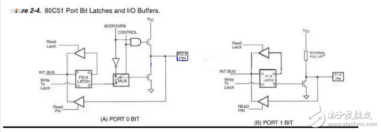
51 structure diagram
In the push-pull structure, it is theoretically possible to realize large output current and improve the load capacity by adjusting the parameters of the pipe. The two pipes have four different combinations according to the on-off state, and the upper and lower pipes are turned on to short-circuit the power supply. In this case, it must not appear in the actual circuit. From the logic circuit, when the upper tube is opened, the IO is directly connected to VCC, and the IO output is low level 0. If there is no external connection in this structure. Pull-up resistor, output 0 is open-drain state (low-resistance state), because the I/O pin is grounded through a tube, not directly connected by wire, and the general MOS also has a mΩ pole conduction in the conduction state. Through resistance.
Exclusion
Whether it is low-resistance or high-impedance, it is relatively speaking. By placing the lower tube in the off state, the GND and I/O ports can be isolated to an open state. At this time, the push-pull pair of tubes is turned off, ignoring If the logic is read, the I/O port pin is equivalent to the internal circuit of the MCU. Considering that there will be a little leakage current when the actual MOS is turned off, it is called “high-impedance stateâ€.
Due to the junction capacitance caused by the PN section of the tube, some data will also be called “floatingâ€. It takes a certain time to charge the capacitor through the I/O port, then the true voltage and surface of the ground at the IO pin. The buoy is similar to the wave, and the magnitude of the voltage is not only related to the external input but also related to time. In the case of high frequency, this phenomenon cannot be ignored.
The single-chip computer crashes and can fly to find the reasons from the following aspects:1. Unexpected interruption. Whether an interrupt is turned on, but does not respond and clear the middle end flag, causing the program to enter the interrupt, causing the illusion of crash;
2. The interrupt variable is not handled properly. If you define some global variables that will be modified in the interrupt, you should pay attention to two problems: first, in order to prevent the compiler from optimizing the interrupt variables, add volaTIle before the variable definition, and then read the interrupt variable before the main loop. The global interrupt should be closed first, to prevent half of the read from being interrupted and modified, and then open the global interrupt after reading; otherwise, the data will be messed up.
3, address overflow, a common error is a pointer operation error. I want to emphasize that the array subscript uses the loop function in the loop function. If the loop variable is not controlled, the array subscript will be out of bounds, and the register of the system will be accidentally modified to cause a crash. In this case, if the crash indicates good luck, otherwise it will be followed. I don't know what a headache is happening.
4, unconditional infinite loop; for example, use while (x); wait for level changes, under normal circumstances x will become 0, just in case, so it is best to add time limit;
5. The watchdog is not closed. Some single-chip microcomputers may accidentally automatically turn on the minimum cycle watchdog even if the watchdog is not turned on, causing the software to reset continuously, causing a crash. This depends on the chip manual. It is best to explicitly clear the program after resetting. The dog closes the watchdog again;
6, the stack overflows. The most difficult problem to find, for small-capacity microcontrollers, try to reduce the level of function calls, reduce local variables, and thus reduce the space required for stacking. When you have tried all the above, you can't solve the problem. Try to put your called less function directly into the calling place and change the local variable that takes up RAM to a global variable. Try it maybe you can. .
Outdoor And Indoor Fiber Optic Cable
Indoor Outdoor Armored Fiber,Outdoor Fiber Cable,Indoor Optic Cable,Indoor Outdoor Cable
Guangzhou Jiqian Fiber Optic Cable Co.,ltd , https://www.jq-fiber.com