Line level signal lines can be divided into two categories: balanced and unbalanced. Balanced signal lines can be identified by their 3-core XLR plugs. Unbalanced signal lines are often terminated with RCA plugs.
The use of balanced signal lines So why use these two incompatible signal lines in audio equipment? For a while, all civilian audio equipment used unbalanced input and output methods; all professional audio equipment used balanced input and output. In fact, balanced input is often referred to as "professional equipment input" to distinguish it from the unbalanced input socket for civilian use. At that time, it was considered that there was no need to use a costly and balanced connection method for civilian audio equipment.
However, after the appearance of the High-End sound, the original idea changed. High-End's audio is no longer using the cheaper unbalanced connections and switching to better balanced connections. In those audio equipments with higher grades, in addition to the unbalanced connection, there are at least several ways to balance the connection. In addition, more and more audio manufacturers are beginning to adopt balanced connections on their products. Therefore, two standards have been adopted on audio equipment - balanced and unbalanced connections. The balanced connection method originally used for professional audio equipment, which is technically advanced and better in sound reproduction effect, has gradually gained increasing application in home audio equipment.
So, what is the balance of wiring? How does it differ from standard RCA plugs and sockets?
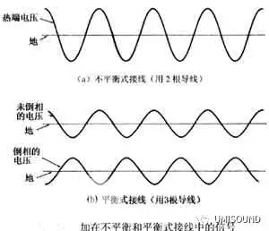
In unbalanced wiring, the audio signal is connected to the RCA plug and the center wiring, while the outside is a grounded shield. There are also some unbalanced signal lines with two signal lines and one shield to shield the shield. If you place this unbalanced signal line near a magnetic field with undulating changes, for example, in the vicinity of the AC power lead, the magnetic field will induce a noise signal in the signal line, allowing people to hear the communication in the speaker. hum.
For professional applications, this hum and noise, as well as buzz, are not acceptable. Therefore, a balanced connection method without such noise interference has been developed. The balanced connection uses three wires, two for transmitting signals and the other for shielding. The two signals are identical but differ in phase by 1800. When the signal transmitted in one of the wires is a positive peak, the signal transmitted in the other wire is just a negative peak, and the third wire is the ground. There are also some balanced signal lines that use three wires with an additional shield.

Balanced and unbalanced wiring

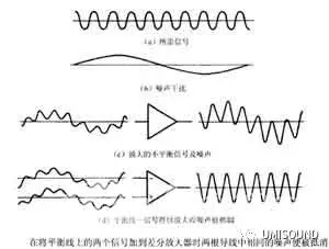
Balanced and unbalanced wiring
When two identical and exactly opposite polarity signals transmitted in the balance line are applied to the differential amplifier in the audio equipment responsible for receiving the signal, all noise in the signal line is suppressed. The reason is that the differential amplifier is only responsible for amplifying the difference between the two signals (see figure). If noise is struck in the line, there will be the same noise in both wires, and the differential amplifier will suppress the noise. This phenomenon of suppressing noise common to the two-pole wires in the balanced signal line is called common-mode rejection.
Depending on the noise rejection at the input of the differential amplifier, it is also characterized by the common mode rejection ratio (CMRR). Note that balancing the signal lines does not leave the noisy signal clean. Balancing the signal line simply suppresses some of the added noise added to the signal line. If the two halves in the balanced signal line have common noise, the common mode suppression will suppress these noises.
In professional applications, a transformer is also used to function as a differential amplifier, that is, the difference between the signals in the two wires is used to suppress the common signal to the two wires. Civil audio equipment uses only differential amplifiers instead of transformers. But the working principle is still the same.
The correct connection is used in the balanced signal line of the XLR connector. Pin 1 is always used as the ground. However, it has not been explicitly stated which wire should be used to transmit an uninverted signal and which one to transmit an already inverted signal. Generally, a wire that transmits an uninverted signal is referred to as a "hot" wire, and a wire that transmits an inverted signal is referred to as a "cold" wire. It has been used so arbitrarily for decades. However, recently the American Audio Engineering Association (AES) announced that it adopts the traditional practice in North America, that is, pin 2 is used as a signal line (hot line) for transmitting uninverted, and pin 3 is used as a signal line for transmitting inverted lines (cold line). ).
It is possible to judge the connection method in the balanced wiring by whether the absolute polarity of the sound system is inverted or not, that is, the pin 2 or the pin 3 should be connected to the "hot wire" (refer to Appendix A1 of this book for absolute polarity). If the sound system has not been inverted, that is, the positive polarity signal on the LP compact disc or CD record is also a positive signal at the input of the speaker, then simply add the balanced signal line to the pin 3 of the power amplifier. The signal is converted to the "hot" signal of pin 2, which causes the system to reverse. When replacing those balanced audio equipment, such as digital processors, preamps, or power amplifiers, you should first find out if the XLR sockets on these new audio equipments are connected to the original equipment.
Although it is also possible to change the absolute polarity of the sound system by changing the connection of pin 3 and pin 2 on the balanced signal line. However, the easiest way to change the absolute polarity of the sound system is to remove the two red and black wires of the speaker cable. If the pin 2 and the pin 3 at one end of the signal line are arbitrarily changed, the other system may not work properly or the polarity may be changed when the polarity is not desired to be changed.
In addition to being able to offset the noise, the balanced border approach tends to be better than the unbalanced connection in terms of playback quality. However, some audio systems connected by balanced signal lines tend to be worse in terms of playback quality than audio systems that are connected in an unbalanced manner. Suppose you have a digital processor on hand that inputs an unbalanced signal from a digital/analog (D/A) converter chip and then converts it into a balanced signal. As a result, it is also advertised by manufacturers as a "balanced output" digital processor. In a digital processor, an unbalanced signal is converted to a balanced signal by a phase splitter that converts one polarity of the signal to another.
The phase splitter has to pass an unbalanced signal through an additional active stage (transistor or op amp) and add more circuitry to the signal path. The output of this balanced digital processor is then applied to the input of the balanced preamplifier. In addition to the best balanced preamplifier, in order to accommodate the gain stage inside the preamplifier, the balanced input signal is first converted to an unbalanced signal in the input stage of the preamplifier. Therefore, a primary active stage is added to the travel of the signal. The unbalanced signal is amplified in the preamplifier and then converted to a balanced signal by a phase splitter.
The balanced output of the preamplifier is then applied to the balanced input of the power amplifier and again converted to an unbalanced signal with a primary active stage. Due to repeated changes in imbalance/balance/unbalance/balance/unbalance, it is inevitable that some undesired circuits are added to the signal stroke. This is why balanced audio equipment is not inherently more vocal than unbalanced audio equipment.
However, it is true that some audio equipment is truly balanced without the use of circuits such as phase splitters. For example, a digital processor can generate a balanced signal in the digital domain, not only without damaging the sound but also gaining some benefits. In addition, four digital/analog (D/A) converters and analog output stages (+ and - left and + and - right channels) can be utilized to convert the balanced signal to an analog signal. As a parent, some preamplifiers also use two identical circuits to process the true balanced preamplifier with inverted and uninverted signals.
It is possible to judge whether it is a truly balanced preamplifier according to the number of volume controls. Preamplifiers that internally process unbalanced signals will have only two volume control devices, one for each of the left and right channels, and a fully balanced preamplifier with four faders: positive and negative. Left channel and positive and negative right channel. Therefore, from the beginning of the digital/analog (D/A) converter in the digital processor to the final stage of the power amplifier, the signals are always in a balanced state.
As with all cases in audio equipment, the best way to verify is to listen and listen. Therefore, when you go to the audio store to buy audio equipment, you should audition both balanced and unbalanced. Let your ears judge whether the sound is connected in a balanced manner or in an unbalanced manner.
Drop Cable,Fiber Drop Cable,Bus Drop Cable,Fiber Optic Drop Cable
Huizhou Fibercan Industrial Co.Ltd , https://www.fibercan-network.com