Four-way answering device circuit schematic introduction:
A circuit consisting of two TTL integrated circuits and a few other components can indicate which of the four buttons is pressed first and prevents latecomers from entering. When one of the four Q outputs is logic "0", the corresponding LED illuminates while the clock input is at a low level to block other entrants. The schematic diagram of the four-way responder circuit is shown in the figure below.
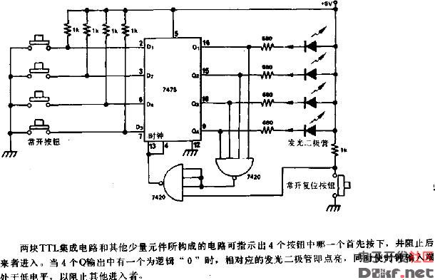
Four-way answering device circuit diagram
All In One Intel I3,I3 All In One Desktop,Pc All In One Core I3,Intel Core I3 All In One
Guangdong Elieken Electronic Technology Co.,Ltd. , https://www.elieken.com