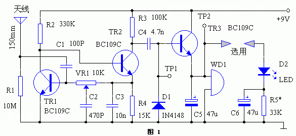
This device is actually an extremely sensitive electrostatic detector that emits an early audible and visual alarm based on the discharge inside the cloud before a lightning strike occurs. An antenna consisting of a short wire can detect a cloud discharge in the range of 3.2 km.
The buzzer sounds an alarm every time a cloud discharge is detected, or an LED (Light-Emitting-Diode) is a semiconductor that converts electrical energy into visible light, which changes the incandescent lamp. The principle of tungsten filament illumination and energy-saving lamp three-base toner illumination, and the use of electric field illumination.) flicker, which can give more time to take measures to prevent lightning strikes such as unplugging the telephone line on the modem, turning off the computer power and unplugging Plug, etc.
working principle
 The circuit principle is shown in Figure 1. The basic feature of this device is to adjust the circuit to approximate the self-oscillation state. The optimum relaxation characteristics are obtained from the bias resistance values ​​shown in the figure. This oscillator is DC coupled and the feedback branch is the collector of transistor TR1 to the base of TR2. The total loop gain is set by a multi-turn (12, 18, 20 turns) preset potentiometer VR1.
 Once the start-up is triggered, the collector of TR2 outputs an oscillation signal of 42 kHz, and is coupled to the base of TR3 via C4, and then rectified by diode D1 to obtain a forward voltage as the TR3 bias to turn it on, thus in TR3. The output DC voltage is output on the emitter, and the self-excited piezoelectric sounder WD1 is driven. If necessary, add a pulsating LED branch to get an alarm.
Capacitor C3 sets the fixed potential of the emitter of TR2, while capacitor C2 connected to the sliding contact of VR1 increases the phase shift when oscillating. The transistor used here is the BC109C, and virtually any small-signal, high-gain transistor of its kind is available.
Debugging At the beginning of debugging, first change the VR1 circuit to start, which can be detected on TR1. The voltage at this point should be 7V peak-to-peak. The test point TR2 should be +6V DC. Now slightly callback VR1 to stop the oscillation. Use a screwdriver to touch the C1 to the antenna. Repeat several times. The alarm should sound for 1 or 2 seconds and then stop. If the sound continues to be audible, the VR1 can be fine-tuned again and then detected until it meets the requirements of only one or two seconds of sounding. Another method is to use a charged plastic ruler (which can be rubbed against dry hair to charge it). Use a finger to approach the plastic ruler to discharge it two meters from the antenna and observe whether it can make WD1 sound 1 Seconds or 2 seconds.
When an alarm occurs, the power consumption depends on the low current sound generator WD1 used, and the power consumption of the whole machine can reach 4 mA.
The circuit is powered by a 9V battery and consumes approximately 600uA in the ready state. A new battery can be continuously monitored for more than a year.
Notonthehighstree Notonthehighstree
Bossgoo(China)Tecgnology.(Bossgoo(China)Tecgnology) , https://www.tlqcjs.com