The electronic probe instrument introduced in this example is to measure the lesions of various parts of the human body by measuring the impedance of each acupuncture point of the human ear. When the human body is sick somewhere, the degree of excitability of the nerve endings at the corresponding auricle sensitive points is increased, the electrical conductivity is enhanced, and the impedance of the acupoint points is lowered, so that the frequency of buzzer sounding becomes high.
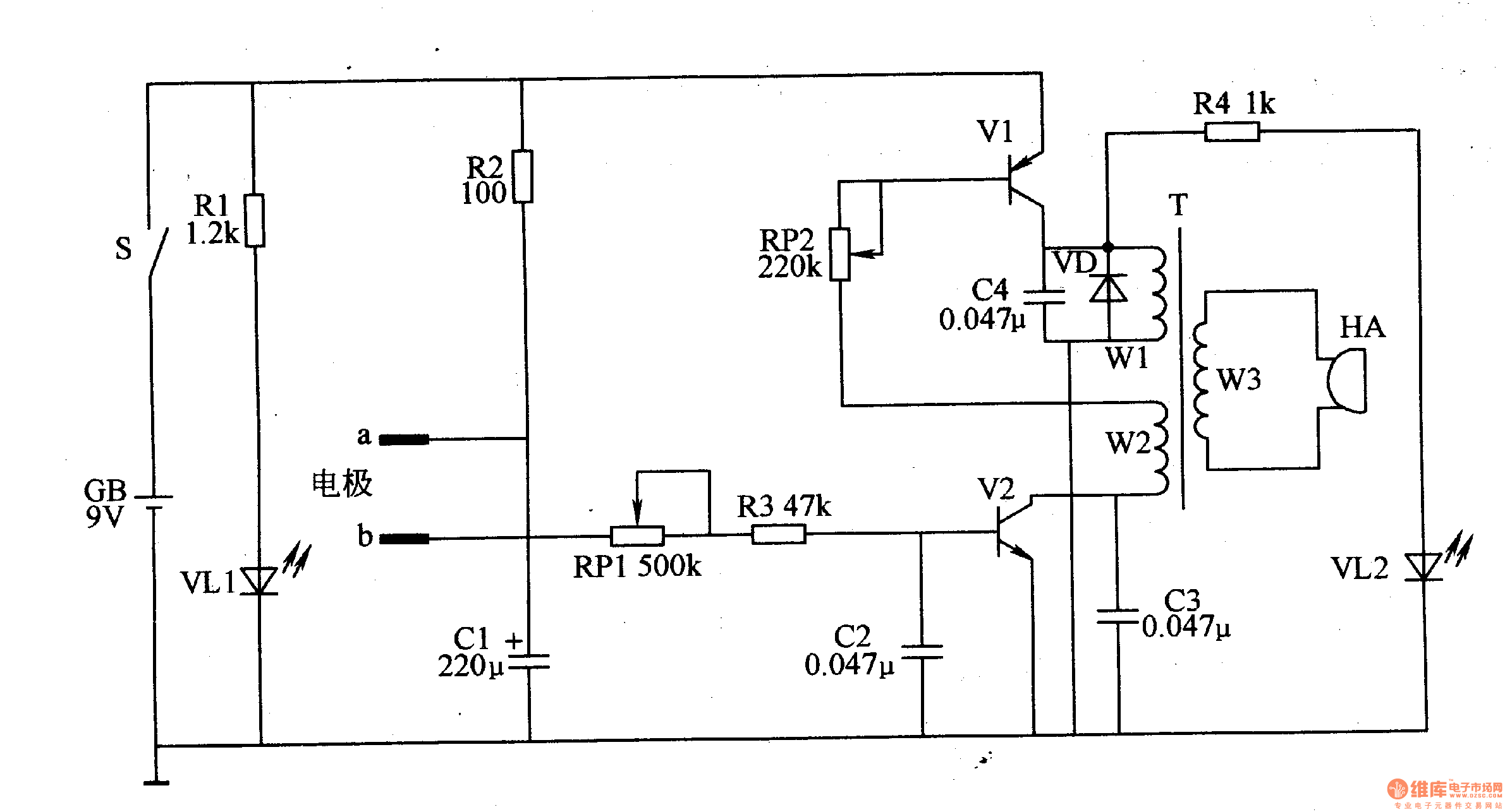
Circuit Operation Principle The electronic probe circuit consists of acupoint detection circuit, oscillator, sound and light indication circuit and power supply circuit. As shown in Figure 9-39.

The acupoint detection circuit is composed of electrodes a, b, resistors R2, R3, a capacitor C1 and a potentiometer RP1.
The oscillator circuit is composed of transistors V1, V2, a potentiometer RP2, a capacitor C2-C4, a diode VD, and a winding W1 of the oscillating transformer T, and a winding W2.
The sound and light indicating circuit is composed of an oscillating transformer T, a resistor R4, a light emitting diode VL2, and a buzzer HA.
The power circuit is composed of a battery GB, a power switch S, a current limiting resistor R1, and a power indicating LED VLl.
When using, turn on the power switch S, hold one electrode in the hand of the subject, and use another electrode to detect the auricle point. The 9V DC voltage of GB is added to the base of V2 via S, R2, acupoint resistance, RPl and R3. The pole makes the oscillator circuit oscillate and the HA beeps. The smaller the acupressure, the higher the oscillation frequency of the oscillator, the higher the flicker frequency and the illuminance of VL2, and the higher the audible tone of HA; on the contrary, if the acupressure is larger, the oscillation frequency of the oscillator is also lower. HA
The tone of the voice is also lower.
Adjusting the resistance of RPl can set the reference value of each acupuncture point when the person is healthy.
Adjusting the resistance of RP2 can change the flicker frequency and illuminance of V愧.
Component selection
Rl-R9 uses 1/4W metal film resistor or carbon film resistor.
Both RP1 and RP2 use small synthetic carbon film potentiometers.
C1 selects aluminum electrolytic capacitor with a withstand voltage of 16V; C2-C4 uses monolithic capacitor or polyester capacitor.
VD selects 1N4007 silicon rectifier diode for use.
Both VLl and VL2 use high-brightness light-emitting diodes of φ3mm.
Vl selects S9015 or 3DG9015 silicon PNP transistor; V2 selects S9011 or 3DG9O11 silicon NPN transistor.
T uses a small semiconductor radio input transformer.
HA uses a piezoelectric buzzer with a sound chamber.
S uses a small single-pole toggle switch.
GB uses 9V laminated battery.
The electrode can be replaced with a multimeter's test lead.
Circuit Operation Principle The electronic probe circuit consists of acupoint detection circuit, oscillator, sound and light indication circuit and power supply circuit. As shown in Figure 9-39.

The acupoint detection circuit is composed of electrodes a, b, resistors R2, R3, a capacitor C1 and a potentiometer RP1.
The oscillator circuit is composed of transistors V1, V2, a potentiometer RP2, a capacitor C2-C4, a diode VD, and a winding W1 of the oscillating transformer T, and a winding W2.
The sound and light indicating circuit is composed of an oscillating transformer T, a resistor R4, a light emitting diode VL2, and a buzzer HA.
The power circuit is composed of a battery GB, a power switch S, a current limiting resistor R1, and a power indicating LED VLl.
When using, turn on the power switch S, hold one electrode in the hand of the subject, and use another electrode to detect the auricle point. The 9V DC voltage of GB is added to the base of V2 via S, R2, acupoint resistance, RPl and R3. The pole makes the oscillator circuit oscillate and the HA beeps. The smaller the acupressure, the higher the oscillation frequency of the oscillator, the higher the flicker frequency and the illuminance of VL2, and the higher the audible tone of HA; on the contrary, if the acupressure is larger, the oscillation frequency of the oscillator is also lower. HA
The tone of the voice is also lower.
Adjusting the resistance of RPl can set the reference value of each acupuncture point when the person is healthy.
Adjusting the resistance of RP2 can change the flicker frequency and illuminance of V愧.
Component selection
Rl-R9 uses 1/4W metal film resistor or carbon film resistor.
Both RP1 and RP2 use small synthetic carbon film potentiometers.
C1 selects aluminum electrolytic capacitor with a withstand voltage of 16V; C2-C4 uses monolithic capacitor or polyester capacitor.
VD selects 1N4007 silicon rectifier diode for use.
Both VLl and VL2 use high-brightness light-emitting diodes of φ3mm.
Vl selects S9015 or 3DG9015 silicon PNP transistor; V2 selects S9011 or 3DG9O11 silicon NPN transistor.
T uses a small semiconductor radio input transformer.
HA uses a piezoelectric buzzer with a sound chamber.
S uses a small single-pole toggle switch.
GB uses 9V laminated battery.
The electrode can be replaced with a multimeter's test lead.
Fiber Optic Cabinet,Fiber Cabinet,Fiber Distribution Cabinet,Outdoor Fiber Cabinet
Cixi Dani Plastic Products Co.,Ltd , https://www.danifiberoptic.com