Due to the addition of negative feedback, even if the power supply voltage applied to the class D output stage varies, it will have little effect on the gain of the amplifier. Therefore, the power supply circuit uses a transformer power supply, and does not regulate the power supply voltage.
In order to pay the power of 00W in the load resistor 8, its power supply voltage should be at least equal to the sum of the maximum amplitude of the output signal and the voltage loss of the class D output stage. The calculation shows that the maximum amplitude of the output signal is about 40V, so the power supply voltage should be at least ± 40V. Taking into account the voltage loss of the output stage and the load characteristics of the power supply, the power supply voltage required at no load should be at least 20% higher than the true ± 40V voltage above, so the power supply voltage at no load is set to ± 50V. By the way, the voltage loss of the output stage includes the on-resistance of the high-power MOS-FET and the DC resistance of the inductance of the low-pass filter at the output end (about 50M sword ┮? Coral Mushroom). Zhai? 00W output is about 0.7V [5 × (0.09 + 0.05)].
The oscillation frequency of this circuit is determined by the delay time and the amount of negative feedback of the integrator formed by the operational amplifier and the subsequent switching circuit. The integrator is a second-order integrator, and increasing the amount of negative feedback in the audio range can improve the distortion rate of the amplifier.
The transistor Tr1 connected to the operational amplifier is a level shift circuit. Since the half-bridge driver integrated circuit IR2010 is a single-supply integrated circuit, the integrator output based on the ground potential needs to be level-shifted based on the negative power supply.
The signal after the level shift enters the inverter of the CMOS logic circuit. The first inverter is used to transform the signal into a signal of this characteristic. In order to input a PWM signal with high time accuracy (pre-pulse and steep edge of the pulse) to IR2010, the pulse waveform is shaped by multiple inverters in the back. This can also reduce the impact of inconsistent logic delay times within the driver IC.
The power supply voltage of the driver integrated circuit is relatively high, the source voltage will change with the switch state, and the internal logic threshold will change, resulting in inconsistent delay times. When this inconsistency is too large, the switching timing of the high-power MOS-FET will be inaccurate, the no-load time will fluctuate, and the distortion rate will eventually deteriorate. In order to reduce this deterioration, the input signal of the driver integrated circuit should be increased, and the rising and falling edges of the input signal should be as steep as possible. In addition, the delay time of the driver IC is part of the delay time required for oscillation.
In order to drive the two high-power MOS-FETs in the next class D output stage, two driving circuits are integrated in IR2010. The power supply of the upper drive circuit is provided by the bootstrap circuit. C28 (3.3 °) and D21 in Figure 1 are the bootstrap capacitor and bootstrap diode. The withstand voltage between the upper drive circuit part and other parts is up to 200V, which is isolated by the junction withstand voltage of 200V.
For IR2010, the on-delay time of the output drive signal is about 30nS longer than the off-delay time, so it is not necessary to set a dead time forming circuit at the input stage of the driver IC. In order to achieve a low distortion rate, the dead time should be shorter. But when the no-load time is too short, the punch-through current will increase.
For digital amplifiers, a surge voltage with a short period and a large peak appears repeatedly during overload. The withstand voltage of the high-power MOS-FET should be at least greater than the sum of the surge voltage and the power supply voltage. After calculation, the minimum withstand voltage of MOS-FET is 130V, so IRFB23N15D with withstand voltage of 150V is selected. The total grid charge of the tube is Qg≤56nC, and the on-resistance RDS (on) ≤90m. ? Shit is too bad? 00kHz digital power amplifier on and off.
For the self-oscillation type digital amplifier, if it can not ensure normal operation above the switching frequency, its various characteristics will deteriorate. In addition, the noise characteristics of the input stage have a greater impact on the noise level at the output, so the operational amplifier should use a low-noise operational amplifier. In this amplifier, LM6361, which is excellent in both high speed and low noise characteristics, is selected.
The use of surface-mounted capacitors helps reduce surge voltage. The output low-pass filter uses a 4th order LC filter. In order to reduce the volume and DC resistance of the inductor coil without distortion, the inductor coil uses a magnetic core with low permeability, and the T-106 core is wound with 38 rounds of? .0 polychlorocarbamate wire . The inductance is 19.5 °.
C6 and R15 are correction circuits that are deliberately connected because the impedance of general speakers will rise at high frequencies.
The small signal circuit of the machine and the power supply of the driver integrated circuit are composed of three-terminal regulator. If the main power supply (VDD and VSS) of the Class D output stage is not necessary, a transformer-type power supply circuit can generally be used, which saves more power than a switching power supply.
Figure 2 is the frequency characteristics of the machine, Figure 3 is the distortion rate characteristics of the machine. In terms of its characteristics, it can not be compared with analog amplifiers, but digital amplifiers are the direction of development, and someday digital amplifiers will become the mainstream of audio amplifiers.

Follow WeChat

Download Audiophile APP

Follow the audiophile class
related suggestion
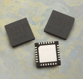
Avago Introduces New High Linear Power Amplifier Module Product Avago Technologies ...
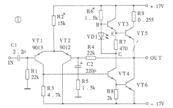
The circuit is shown in Figure 1. The chip IC uses the LM1875 of the American NS company, which has a soft tone and low distortion (0.015% ...

The word "Monster" has both positive meaning and ...
If an "audiophile" is a group of people who are never satisfied with the sound and "loved the new and the old" with the audio equipment. Then just rely on these so-called "fever spirits" ...
First, the circuit principle and characteristics 1. Power amplifier part (see Figure 1)
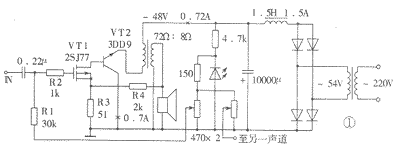
There is a well-known saying in the Hi-Fi world that is "briefness first." This means that if ...
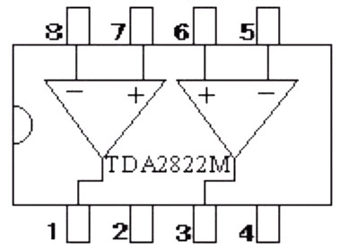
Simple and practical TDA2822M integrated power
TDA2030 is ...

STK465 thick film ...

This RF power amplifier can output 2-3 channel signals, covering an area of ​​about one square kilometer, is ...
![[Photo] 15w RF power amplifier](http://i.bosscdn.com/blog/20/06/41/521040781.gif)
![[Photo] Broadband high frequency power amplifier](http://i.bosscdn.com/blog/20/06/41/520536801.jpg)
Low frequency power amplifier
![[Photo] TDA2030 audio power amplifier](http://i.bosscdn.com/blog/20/06/41/5131012891.gif)
Looking at the Hi-Fi amplifiers currently on the market, the output power is 100W ...
![[Photo] Transistor 15W Class A Power Amplifier](http://i.bosscdn.com/blog/20/06/41/513102891.gif)
With the newly launched LM4651 and LM465 from National Semiconductor ...
![[Photo] 125W Class D Subwoofer Power Amplifier](http://i.bosscdn.com/blog/20/06/41/513100868.jpg)
![[Photo] Mark Levinson No. 30 ...](http://i.bosscdn.com/blog/20/06/41/513544752.jpg)
EL34 (6CA7) was first launched by Philips in 1956 ...
![[Photo] 45W transistor tube hybrid power amplifier](http://i.bosscdn.com/blog/20/06/41/513531952.jpg)
This article cleverly combines the electronic tube EL34 and the transistor (op amp), ...
![[Photo] 32W hybrid audio power amplifier](http://i.bosscdn.com/blog/20/06/41/513526493.jpg)
The pre-amplifier adopts a European-made TESLA brand low noise high cheek double transistor ...
![[Photo] Gallstone hybrid power amplifier using switching power supply](http://i.bosscdn.com/blog/20/06/41/513524776.gif)
"Simple" means the circuit of the amplifier is simple, making it easier, as long as the picture ...
![[Photo] Simple fool power amplifier](http://i.bosscdn.com/blog/20/06/41/513432946.jpg)
1. Description: & nb ...
![[Photo] LM386 low voltage audio power amplifier ...](http://i.bosscdn.com/blog/20/06/41/513417261.gif)
The Class A transistor power amplifier has a warm and sweet tone, which makes people tempted. But the temperature rise of Class A amplifier ...
![[Photo] Class A power amplifier using SAP15N / P audio pair tube ...](http://i.bosscdn.com/blog/20/06/41/513346769.gif)
The circuit is shown in Figure 5, ...
![[Photo] Using TDA7294 and 2SA1216 / 2S ...](http://i.bosscdn.com/blog/20/06/41/4233420295.gif)