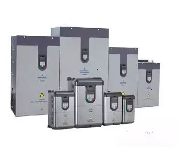
Under the current production conditions, when using the inverter to form an automatic control system for control, in many cases, it is necessary to use plc and inverter together, such as bearing cleaning, wrapping paper printing, PCB board making, etc. The PLC can provide various control signals and command on/off signals through output points or by communication. Here are some things to note when using the inverter and PLC.
1. Input of switch command signal The input signal of the inverter includes switch type command signals for controlling the running states of running/stopping, forward/reverse, segment speed, and jog. The inverter usually uses a relay contact or a component with a relay contact switch characteristic (such as a transistor) to connect to the PLC to obtain an operating status command. When using relay contacts, it often causes malfunction due to poor contact; when using transistors for connection, it is necessary to consider the voltage and current capacity of the transistor itself to ensure the reliability of the system.
When designing the input signal circuit of the inverter, it should also be noted that when the input signal circuit is not connected properly, the inverter may malfunction. For example, when the input signal circuit uses an inductive load such as a relay, the inrush current generated by the relay opening and closing may cause damage or failure of the internal components of the inverter, which may cause the inverter to malfunction. Therefore, this situation should be avoided as much as possible. When the input switch signal enters the inverter, crosstalk between the external power supply and the inverter control power supply (DC24V) sometimes occurs. The correct connection is to use the PLC power supply to connect the collector of the external transistor to the PLC via a diode.
2. Input of numerical signal There are also some input of numerical signal type (such as frequency, voltage, etc.) in the inverter, which can be divided into analog input and analog output. The analog input is externally given via the terminal block and is usually input via a voltage signal of 0 to 10V/5V or a current signal of 0/4 to 20 mA. Since the interface circuit varies depending on the input signal, the output module of the PLC must be selected according to the input impedance of the inverter.
When the voltage signal range of the inverter and PLC is different, for example, the input signal of the inverter is 0~10V, and the output voltage signal range of the PLC is 0~5V; or the output signal voltage of one side of the PLC is 0~10V. When the input voltage signal range of the inverter is 0~5V, due to the limitation of the allowable voltage and current of the inverter and the transistor, it is necessary to connect the resistor in parallel and in series to limit the current or divide the partial voltage. In order to ensure that the corresponding capacity of the PLC and the inverter is not exceeded when opening and closing. In addition, it should be noted that the control circuit and the main circuit should be separated when connecting, and the control circuit should preferably use a shielded line to ensure that the noise on the side of the main circuit is not transmitted to the control circuit.
Note: The input impedance of the PLC side should be such that the voltage and current in the circuit do not exceed the allowable value of the circuit to ensure system reliability and reduce errors.
In addition, when using PLC for sequential control, it takes time to perform data processing, and the order of arrangement and the use of instructions are different when the program is written. This will cause the system to have a certain time delay during operation, so in the case of more precise control. The above factors should be considered.
Because the inverter will generate strong electromagnetic interference during operation, in order to ensure that the PLC does not malfunction due to the noise generated by the main circuit breaker and switching device of the inverter.

Therefore, the following points should be noted when connecting the inverter to the PLC:
(1) The PLC itself should be grounded according to the specified wiring standards and grounding conditions, and care should be taken to avoid using the common grounding wire with the inverter, and to make the two separate as much as possible when grounding.
(2) When the power supply condition is not good, connect the noise filter, reactor, and noise reduction device to the power supply module of the PLC and the power supply line of the input/output module. In addition, if necessary, The corresponding action should also be taken on the input side of the inverter.
( 3) When installing the inverter and PLC in the same operation cabinet, the wires related to the inverter and the wires related to the PLC should be separated as much as possible.
(4) Improve the level of noise interference by using shielded wires and twisted pairs.
Our wire and cable requires for product quality certification documents from the supplier, The wiring shall have the factory quality certificate documents, including: certificate of quality (the certificate has the production license number and the "CCC" certification mark), test report and the "CCC" certification certificate; he quality certificate of electric wire shall be the original, if it is a copy, the copy shall be consistent with the original content, with the official seal of the original storage unit affixed, indicating the place where the original is stored, and the signature and time of the handler; The manufacturer shall have the business license of enterprise legal person.
Automotive Wire Connectors,Waterproof Wire Connectors,Wire Connectors,Wire Harness Connectors
Dongguan YAC Electric Co,. LTD. , https://www.yacentercn.com