Commercially available emergency lights are equipped with overcharge protection, but often have no discharge protection. If the lead storage battery is over-discharged, the lead sulfate crystal will be formed into a larger body, which not only increases the resistance of the plate, but also makes it difficult to re-recharge it during charging, directly affecting the capacity and life of the battery. The circuit provided here protects the battery from overcharging and overdischarging. When the AC power is active, the load is supplied from the regulator; if the AC power fails, the load is automatically transferred to the 6V battery. When the AC power is restored, the load returns to being powered by the regulator and the battery begins to charge.
This article refers to the address: http://
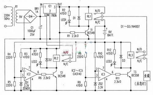
The entire circuit can be divided into four parts: power supply, switching circuit, over-discharge protection circuit, and over-charge protection circuit.
The AC power supply supplied by the power supply is stepped down by the transformer X1, rectified by the bridge rectifier BR1, and filtered by the capacitor C1, and then stabilized into a 6V power supply by the chip 7806 (IC1).
The switching circuit is composed of components such as a transistor T1 and a relay RL1. When the AC power is enabled, T1 is turned on, so that RL1 (6V, 100Ω) is attracted, and green LED1 is illuminated, indicating that the AC power is valid. At the same time, the regulator output is connected to the load via the normally open contacts N/O of RL1 and the normally closed contact N/C of RL3, while the 6V battery begins charging via the normally closed contact N/C of RL2.
When the AC power fails, T1 is turned off. RL1 is released. As a result, the load is changed from the normally closed contact N/C of RL1 from the 6V battery. At this time, LED1 is off, indicating that the AC power supply is no longer present.
The battery over-discharge protection circuit is composed of IC3, T3, RL3 and other components. When the battery is over-discharged (less than 5.5v), the voltage on the inverting input (2) of IC3 is higher than the voltage on its non-inverting input (3). At this time, the output of IC3 is low, T3 is turned on, RL3 (5V, 100Ω pull-in, the load is disconnected from the 6V battery due to the contact N/C separation, thus avoiding over-discharge. At the same time, LED3 emits light, indicating that the battery is in an excessive discharge state. When the AC power is restored, the battery passes through The contact N/C of RJ2 starts to charge. When the battery voltage reaches 5.5v, the output of IC3 returns to high potential. T3 is cut off, RL3 is released, and the load is connected to the output of the regulator.
The overcharge protection circuit of the battery is composed of IC2, T2, RL2 and other components. When the AC power is active, and the battery voltage is lower than 6.6V. Since the voltage on the inverting input terminal 2 of IC2 is higher than the voltage on the non-inverting input terminal 3, the output of IC2 is low, T2 is turned off, and RL2 (6V.100Ω) is kept in the released state. At this point the battery continues to charge through the N/C contact of the RL2. Once the battery voltage reaches 6.6V. The output of IC2 goes high, T2 turns on, RJ2 pulls in, and charging stops. At this time, the LED 2 emits light, indicating that the battery is in an overcharged state. In the figure, D2 and D3 respectively protect RL2 and RL3 from the impact of back electromotive force.

ANC Earphone
ANC earphone means Active Noise Cancellation (ANC) .The noise cancelling earbuds uses noise-cancelling speakers to reduce unwanted background noise.This allows the user to more clearly hear the nature of the sound.

ANC Earphone,Htc True Wireless Earbuds,Anc Wireless Earbuds,Best Anc Earbuds 2021
Pogo Technology International Ltd , https://www.pogomedical.com