It is becoming more and more difficult to design a smartphone antenna that can be used in existing 4G and meets future 5G requirements, as it must be able to transmit and receive over all frequency ranges. But the solution is the "multiple input multiple output" (MIMO) antennas currently used in advanced designs, or multiport antennas, which analyze frequency bands in an inexpensive but efficient manner.
Unfortunately, today's experienced antenna designers often use "black magic" (their personal experience and insights) to speculate on what the optimized antenna configuration should look like, then simulate for all relevant factors, sometimes it takes Computer work time for a whole week. And if the results are not good, they will have to do it again until they get the ideal design - but never know how much their design is far from the optimal configuration.
Researchers at North Carolina State University (NCSU) are now finding a better solution for this. They did not perform detailed simulations through the most experienced "black magic" RF experts, but solved the optimized antenna configuration problem by simply eliminating all the most important parameters to simplify the problem to its basic principles. These algorithms can be executed in minutes without having to spend weeks, allowing RF experts to repeat the configuration until optimization is achieved. Then, you can use the traditional simulator to perform more detailed verification of the design before manufacturing.

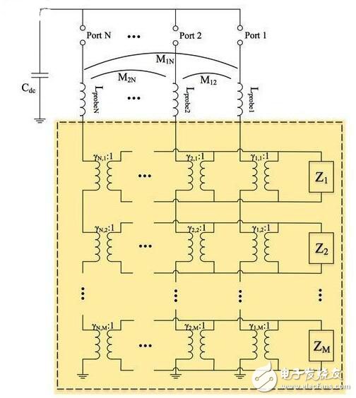
Typical circuit diagram of 3-port microstrip planar antenna
“Our motivation was originally to study multi-port antennas and to understand how it works in fundamentals,†explains University of North Carolina professor Jacob Adams. “Our research work will be very important for 5G because we are not Using traditional full-wave simulation to implement per-port configuration, the antenna is modeled as a resonator in various modes, then a virtual æ’å…¥ is inserted and its location is evaluated."
The key to this approach is to first model the antenna without input—the general technique usually does not do this—and the result is a special fundamental resonance mode that expresses the antenna's ability to respond to various modes.

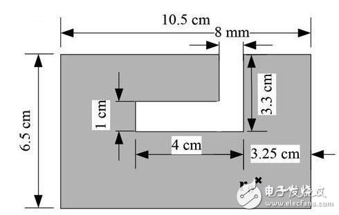
Typical geometry of a slotted patch antenna
“We are developing a pathless antenna modeling approach that allows us to import sources and quickly observe their responses,†Adams said. “The final mode of obtaining excitation depends on the type and location of the stimulus received. â€
Using this method, the researchers found the best antenna configuration and avoided neglecting the materials used. According to Adams, the traditional approach lacks an analytical approach that can be found to be absolutely optimized, "but we can define what the optimal configuration should be, propose a path that is available, and quickly test how close it is to the theoretical value of the optimization."

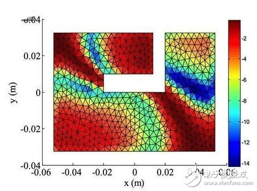
North Carolina State University's first resonant frequency (856.5-MHz) decibel (dB) map, where the optimized antenna mounting position is denoted by P and the worst position is denoted by W
Once the approximation algorithm finds the optimal configuration, the RF engineer can perform the traditional algorithm, adding material properties, the double geometry of the feed, and other factors that the NCSU approximation algorithm ignores. Compared to just executing the traditional algorithm - about 116 hours, this method takes only 15 minutes, which saves a lot of time, because all trial-and-error has been done by NCSU mode.

NCSU's second resonant frequency decibel map
Pcb Terminal Block,Pcb Barrier Terminal Blocks,Pcb Terminal Block Connector,Barrier Terminal Blocks And Connectors
Sichuan Xinlian electronic science and technology Company , https://www.sztmlch.com