With the widespread popularity of the Internet and the rapid development of communication technology, a large number of Internet applications based on TCP/IP can be deployed on embedded platforms, and various embedded devices can be connected to the network like PCs. The embedded Internet technology (EI) developed from this solves the problem of connectivity between different networks and the Internet, making it possible to remotely access, control and manage embedded devices in the network through the embedded Internet. At present, efficient and reliable centralized remote control and management of embedded devices distributed on the Internet has become a relatively high-end topic in embedded technology.
This article discusses in detail a remote monitoring system that controls online embedded equipment through embedded Internet technology. This system adopts the client/server (C/S) model. The embedded Web server (EWS) function is realized by simplifying the TCP/IP protocol stack. Install the EWS into the device, so that embedded devices can be interconnected via the Internet, and a network management page can be provided, so that users can use a standard web browser to remotely access, control and manage many devices online, limiting time and distance drop to lowest.
1 Control system architectureMicroprocessors (MPU) and microcontrollers (MCU) are used to monitor and control embedded devices and become the core of embedded systems. In order to communicate between different MPUs/MCUs, many industrial projects adopt communication standards such as RS-232, RS-485 and CAN, but the communication speed and distance of these channels have greater limitations. If you want to interconnect them with the Internet The support of a special embedded gateway is required, which causes great inconvenience to actual use. EI is an interconnection technology used for embedded devices to access the Internet. It enables embedded devices to access the Internet easily and reliably.
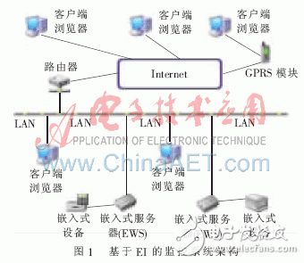
In order to enable embedded devices to connect to the Internet and allow users to operate it through a standard Web browser, the key technology of EI is to enable embedded devices to support HTTP services and have the function of a Web server. For network users, EWS provides a web-based graphical interface to facilitate unified and standardized management of a variety of embedded devices connected to the Internet, without the need for special dedicated protocols and management software. The architecture of the monitoring system is shown in Figure 1.

In this system, EWS is embedded in the device and connected to the device through a serial port. Each device has its own IP address and is connected to the local area network (LAN) through the RJ-45 interface through the internal EWS (in this experiment, the LAN is Ethernet). On the one hand, EWS reads device status information and sends it to local or remote users; on the other hand, it receives control commands and sends them to the device. And a wider range of wide-area network communication can be realized through the Internet or mobile communication network.
2 Design and implementation of EWS2.1 Software architecture
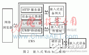
This system adopts browser/server structure to realize, including two parts-web browser and EWS, EWS realizes its function through embedded network technology. In practical applications, the EWS is configured in the embedded device and exists as a part of the device, which allows the device to directly access the network without further modification or configuration. At the same time, EWS also has built-in components such as TCP/IP protocol stack, embedded file system, device gateway and hardware interface, and its basic architecture is shown in Figure 2.

In this architecture, the embedded file system stores and manages the pre-configured monitoring pages. The embedded device gateway realizes the mutual conversion between TCP/IP and the actual use of the specific device's own control protocol, thereby realizing two-way transparent communication. Two networks with different structures can be connected to each other through embedded devices, and the hardware interface is responsible for the connection between EWS, hardware devices and the network.
When this system is working, first EWS receives the request based on the website of the client from the local area network and responds to the request. By responding to the monitoring web interface configured in advance and stored in the embedded file system, the user can send instructions to the remote device through a standard browser. The instruction is received by the device gateway after being transmitted via the Internet, and the device gateway translates it into a dedicated instruction and further transmits it to the hardware device itself. At the same time, device data or signals are also transmitted to the remote client for users to view.
2.2 Simplify the TCP/IP protocol stack
Embedded Internet technology effectively solves the problem of embedded devices accessing the Internet, enabling these devices to be remotely accessed and controlled through ordinary browsers. How to embed the TCP/IP protocol stack into the device is the key to solving the problem . The traditional TCP/IP protocol stack is relatively large and complex and requires fixed system resource support. However, most embedded devices use 8-bit or 16-bit MCUs, and their computing power and system resources are relatively weak. If the traditional TCP/IP protocol stack is directly connected to the device, most of the computing time and system resources will be occupied, which has a great impact on the overall performance of the system. In order to solve this contradiction, the mature LWIP protocol stack was selected according to the specific conditions to realize the network function while designing the monitoring system, while minimizing the consumption of system resources and improving the reliability.
LWIP (Light-weight Internet Protocol) is an open source TCP/IP protocol stack for embedded systems developed by Adam and Dunkels of the Swiss Academy of Computer Sciences. From the system requirements, LWIP can be transplanted to the operating system, and can run independently without an operating system. In addition, the LWIP protocol stack reduces the occupation of RAM while maintaining the main functions of the TCP/IP protocol. Only tens of KB of RAM and 40 KB of ROM can run, making the LWIP protocol very suitable for use in embedded systems [4]. Its main features are:
(1) Support IP forwarding under multiple network interfaces.
(2) Support ICMP (Internet Control Messages Protocol).
(3) UDP (User Datagram Protocol) with experimental extensions is included.
(4) Transmission control protocol TCP (Transfer Control Protocol) including congestion control, RTT estimation and fast recovery and fast forwarding.
(5) It has a specially provided internal callback application programming interface Raw API (Application Programming Interface), which can be used to improve application performance.
(6) With optional Berkeley interface API (in the case of multi-threading); it can support dynamic host configuration protocol (DHCP) and dynamically assign IP addresses.
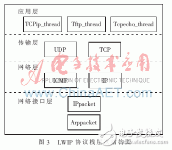
The internal layered structure of the LWIP protocol stack is shown in Figure 3. After analysis and actual testing, the protocol stack can run smoothly on a 16-bit MCU and can meet all the functional requirements of the monitoring system.

2.3 Embedded file system
In actual work, according to the request of the client browser, EWS sends the corresponding management page to the client. Therefore, for this system, it is necessary to realize the storage and access management of these page files. For this reason, an embedded file system is built in this system to facilitate the management and access control of the page files and other data in Flash. .
In this system, the file system manages files based on their name, length, and starting address. Structurally, the file system does not use multi-level directories, but lists all files under a single root directory. Although this kind of directory structure is not suitable for file systems with rapidly increasing capacity, the speed of locating and extracting files has a greater advantage.
When the files of the monitoring system need to be changed significantly, the file system can be reconstructed through the TFTP protocol. Although the structure and function of this file system are relatively simple, it can meet the needs of embedded Internet in most cases, that is, frequent file access and fewer file changes.
3 Practical application and testingThis monitoring system has been applied in radio signal monitoring projects. Its hardware platform is a remote unmanned monitoring station, which receives user instructions and uploads monitoring data through the Internet. In this project, the measuring instrument is connected to the Internet through the EWS in the monitoring system, and the measuring instrument uses the Megatec protocol. The remote user instructions are translated by EWS into Megatec protocol format and then handed over to the instrument for execution, and the monitoring data is sent back to the client at the same time. From a functional point of view, customers can perform the following operations:
(1) Obtain the measurement data of the remote unmanned station in real time or regularly.
(2) Real-time monitoring of the status and parameters of the remote unmanned station.
(3) Configure the operating parameters of the remote unmanned station in order to meet the predetermined or unexpected needs.
The main monitoring interface in this project is shown in Figure 4.

This paper studies and implements a remote monitoring system based on EI. The system uses a client/server structure. By building an embedded Web server in the embedded device, the monitoring system allows the embedded device to directly access the Internet, and at the same time, the user can use a standard web browser to remotely manage and control the embedded device. This system has been practically applied in radio monitoring projects, and has successfully obtained monitoring data from remote unmanned monitoring stations and can control the monitoring stations. As a result, all its design functions are realized. The actual measurement data shows that the data response delay of the monitoring system is milliseconds. This indicator can meet the needs of most remote monitoring projects.
Basic Features
1. The terminal has universal mounting feet so that it can be installed on U-rail NC 35 and G-rail NC32.
2. The closed screw guide hole ensures ideal screwdriver operation.
3. Equipped with uniform accessories for terminals of multiple cross-section grades, such as end plates, grouping partitions, etc.
4. Potential distribution can be achieved by inserting a fixed bridge in the center of the terminal or an edge-plug bridge inserted into the wire cavity.
5. The grounding terminal and the N-line slider breaking terminal with the same shape as the common terminal.
6. Using the identification system ZT, unified terminal identification can be realized.
7. The rich graphics enhance the three-dimensional sense of the wiring system.
Din Rail Terminal Block,Din Rail Fuse Terminal Block,Din Rail Busbar Terminal Block,Din Rail Power Terminal Blocks
Sichuan Xinlian electronic science and technology Company , https://www.sztmlchs.com