Avionics refers to the sum of all electronic systems on an aircraft. One of the most basic avionics systems consists of multiple systems for communication, navigation and display management. There are many types of avionics, ranging from searchlights on the simplest police helicopters to complex, such as airborne warning platforms, for different purposes. The avionics system also has its own characteristics, which are constantly changing with the development of avionics.
Introduction to MIL-STD-1553Look at the data transfer path, the MIL-STD-1553 bus structure in Figure 1. MIL-STD-1553 is a military standard that defines the electronic and protocol characteristics of a data bus. As a bus that has been widely used in military and commercial applications for more than 25 years, and conforms to the MIL-STD-1553 standard, it can transmit data with high accuracy and reliability at a rate of 1 Mbit/s.
According to the MIL-STD-1553 standard, the bus structure consists of three different hardware:
Bus Controller - The bus controller is the only hardware device on the bus that allows commands to be issued on the data bus and is responsible for directing data streams in the data bus. If several terminals can implement the functions of the bus controller at the same time, only one of them can be active at the same time.
• Bus Monitor – A bus monitor is a terminal that monitors the exchange of information on the bus. It can be used for flight test recording, flight troubleshooting, maintenance logging and mission analysis, as well as an alternate bus controller with enough information to take over the bus controller. However, the bus monitor is a passive device that does not report the status of the information being transmitted.
Remote Terminals - Each remote terminal includes the electronics and supporting middleware necessary to transfer data between the data bus and the subsystem. For MIL-STD-1553, the subsystem is the sender and receiver of the transmitted data. These terminals cannot be used as bus controllers or bus monitors.
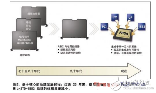
MIL-STD-1553 system implementationLike other military networking technologies, the MIL-STD-1553 test and simulation implementation in the avionics market has evolved from a massive DEC Unibus card to a 19-inch rack-mounted component to a VME and PCI system. The smaller, more integrated multi-channel backplane now has a smaller, more integrated PCMCIA interface. Figure 2 depicts the implementation of a dedicated MIL-STD-1553 ASIC chip manufacturer that evolves from discrete protocol and transceiver chipset simplification to a single small, low power ASIC.

In the past, typical MIL-STD-1553 systems were typically composed of multiple COTS components. MIL-STD-1553I/O is typically provided by a single source ASIC with internal processing capabilities that provide message processing and buffering. And encoding and decoding the MIL-STD-1553 bit stream. The ASIC may or may not have a transceiver component that provides a physical interface to the MIL-STD-1553 bus. Each ASIC provides this capability for a dual redundant MIL-STD-1553 channel, so systems supporting multiple MIL-STD-1553 channels require multiple ASICs and transceivers. The connection to each MIL-STD-1553 bus is achieved via an onboard transformer. Finally, the MIL-STD-1553 ASIC is connected to the host system by one or several programmable FPGA devices and provides additional system functions such as other I/O, memory access and processor interfaces.
FPGAs come in a variety of densities and are usually measured in logical units or gates. They come in a variety of form architectures that provide a rich set of I/O pins for use. The FPGA can also provide internal memory. For example, the current state-of-the-art FPGA storage capacity introduced by Xilinx has increased about 10 times compared to three years ago. It also increases internal speed and reduces costs.
The massive storage and function of modern FPGAs make it the ideal choice for MIL-STD-1553 design. At its core are pre-defined, tested features that can be applied to FPGA designs. There are many reasons for engineers to choose IP designs for MIL-STD-1553 implementation, including:
Waste Component Management - Using IP cores can significantly reduce the risk of abandonment. Designers are not tied to a particular component or even an FPGA manufacturer. This is in stark contrast to the proprietary MIL-STD-1553 protocol ASIC and processor (and its manufacturing method) that can be abandoned at any time. After implementing the FPGA on the circuit, the design can be ported to the latest FPGAs, generally without changing its functionality, reducing the software modifications (usually the most costly part of the project).
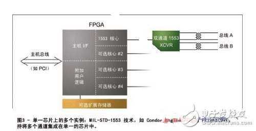
Reduces size, improves reliability, reduces power consumption and weight—combines multiple functions, including processor, I/O, MIL-STD-1553, and backplane circuitry into a single IC, dramatically reducing component count , board space and heat load. This increases reliability and thus increases MTBF. Reducing the number of components can reduce the weight, space, and power requirements of the flight equipment system. As shown in Figure 3, designers can combine multiple functions into a single logical device, reducing the number and size of components.

Reduce costs – due to the implementation of the FPGA core, the cost of production and lifecycles will decrease over time. FPGA prices have historically declined significantly as the project progressed, while ASICs have risen in price during long-term production. Many avionics systems have adopted FPGAs in their designs, and a MIL-STD-1553 core instance can be easily integrated into existing chips or other denser chips in the same family. The multi-channel instance is concentrated in a single FPGA to further save cost, because only a single channel interface can be accommodated in a single FPGA.
Easy to reprogram – Core implementations significantly reduce design risk by supporting reprogramming of field hardware. If the system requirements change, or if an error is to be fixed, the FPGA-based design can be upgraded under software control. This flexibility also allows for a new distinction between hardware and software after the hardware is constructed. For example, if during the integration phase it is found that the software is not responding effectively to a real-time event, the function can be moved down to the FPGA level, thus converting the functionality originally implemented by the software into a hardware function.
Adapt to a wide range of aircraft – flexible, reprogrammable solutions for flight test line replaceable parts (LRU) designed for a wide range of aircraft structures or for multi-purpose foundations. Since the various bodies of USAF and NATO use the protocol separated from the MIL-STD-1553B standard, the LRU of various organisms needs a flexible and programmable design. Some designs implement data sets that are addressed by addressing with a special subaddress or pattern code protocol. Many fixed-wing and rotatable wing aircraft use the older MIL-STD-1553A and MIL-STD-1553BLRU, which requires the bus controller and bus monitor to handle different protocols.
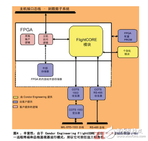
Core-based implementation of MIL-STD-1553 system designThe power of modern FPGAs makes them ideal for MIL-STD-1553 design, which is why CondorEngineering introduced FlightCORE. FlightCORE is a MIL-STD-1553IP that allows designers to easily implement a copyright-free instantiation design in a variety of Altera and Xilinx FPGAs. In most cases, FlightCORE1553 can be successfully integrated in two days using Xilinx Synthesis Technology (XST) or Altera Quartus II Integrated Synthesis Technology (QIS). As shown in Figure 4, the user only needs to integrate the IP core of CondorEngineering with its own logic and the individualized module of CondorEngineering (3mmx3mm) to achieve high performance MIL-STD-1553 design. FlightCORE also allows developers to choose the size of the memory to exactly match its system requirements. Figure 4 also shows that internal storage and/or external dual port random access memory can be implemented. The product also provides all the necessary components for Manchester II encoding and decoding, information protocol verification and legalization, and simple shared storage architecture for interface control and programming. Simply add an external transceiver, such as the standard COTSMIL-STD-1553 or rs-485/' target='_blank'>RS-485 transceiver.

Fiber Optic Fast Connector,Optic Fiber Quick Connector,SC fiber optic connector,Fiber Optic Connector Kit,Fiber Optic Cable Adapter
Sijee Optical Communication Technology Co.,Ltd , https://www.sijee-optical.com